
Robot eye-on-hand system structured light plane parameter calibration device and method

A system structure and robot technology, which is applied in the field of structured light plane parameter calibration devices based on linear primitives, can solve the problems that the coplanarity of feature points cannot be well guaranteed, the accuracy of light plane calibration is affected, and the operation process is cumbersome. The effect of improving calibration efficiency, reducing labor intensity and avoiding injury

Active Publication Date: 2013-02-13
INST OF AUTOMATION CHINESE ACAD OF SCI +1
View PDF5 Cites 96 Cited by
  • Summary
  • Abstract
  • Description
  • Claims
  • Application Information

AI Technical Summary

Problems solved by technology

The above two methods realize the calibration of structured light parameters by selecting feature points on the stripes, which have the following limitations: first, the method of extracting calibration feature points can only obtain a limited number of calibration feature points; There is a certain width of the stripes. In the image processing stage, the method of extracting feature points is easy to cause measurement errors, and the coplanarity of the feature points cannot be well guaranteed, thus affecting the calibration accuracy of the light plane; third, for the free moving plane The calibration method of the target requires personnel to move the target to obtain the feature points, and each time the target is moved, the power of the laser needs to be manually turned on and off, and the operation process is cumbersome.

Method used


Image

  • Robot eye-on-hand system structured light plane parameter calibration device and method
  • Robot eye-on-hand system structured light plane parameter calibration device and method
  • Robot eye-on-hand system structured light plane parameter calibration device and method

Examples


Embodiment Construction

[0024] In order to make the object, technical solution and advantages of the present invention clearer, the present invention will be described in further detail below in conjunction with specific embodiments and with reference to the accompanying drawings.

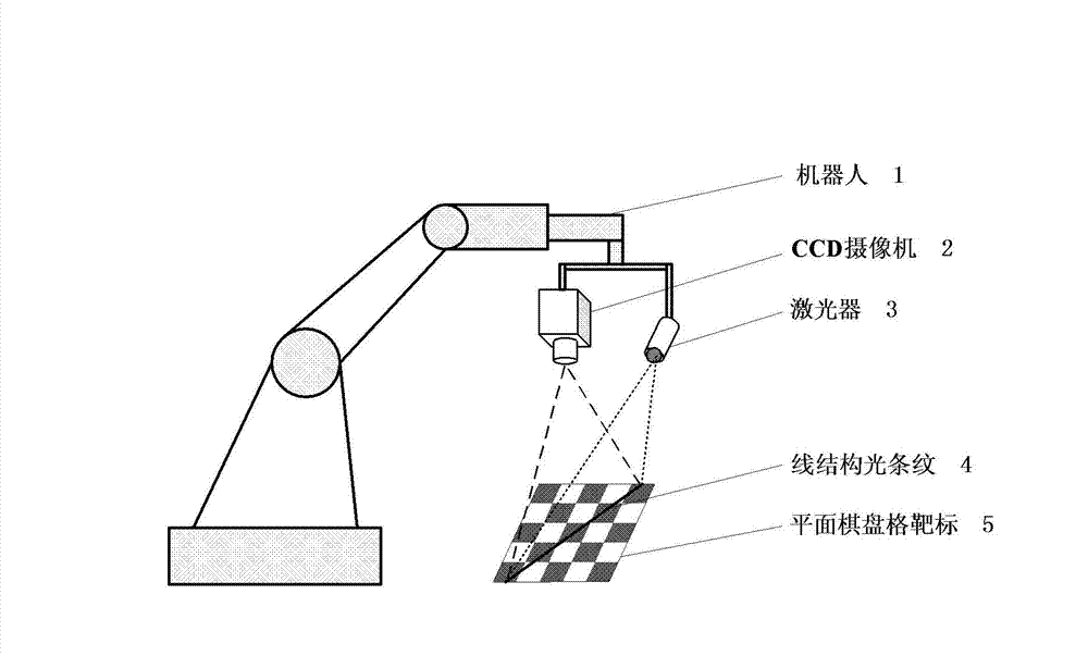
[0025] figure 1 It is a schematic diagram of the robot hand-eye system structured light plane parameter calibration device of the present invention, such as figure 1 As shown, the robot hand-eye system structured light plane parameter calibration device of the present invention includes: a robot 1, a camera 2, a laser 3 and a planar checkerboard target 5, wherein the camera 2 and the laser 3 are fixed at the end of the robot 1 , constitute a robotic structured light vision sensing system; the planar checkerboard target 5 is placed in the calibration area below the camera 2 and the laser 3; by adjusting the pose of the end of the robot 1, the laser 3 A beam of laser plane is projected onto the planar checkerboard target 5...


PUM


Abstract

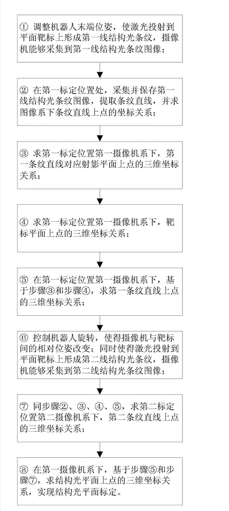
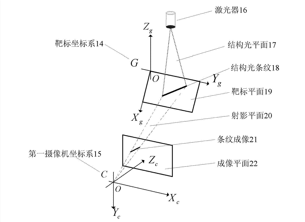
The invention discloses a robot eye-on-hand system structured light plane parameter calibration device and a method. According to the device, a camera and a laser device are installed at the tail end of a robot to form a robot eye-on-hand system, and on the premise of obtaining camera intrinsic parameters, plane parameters of structured light projected by the laser device are calibrated, and thereby structured light three-dimensional vision measurement can be achieved. The robot eye-on-hand system structured light plane parameter calibration method includes that a plane checkerboard target is placed in a calibration area, laser lights are projected on the target to form a first line structured light stripe, the robot is controlled to move in a constraint mode so as to project the laser lights to another position of the target to form a second line structured light stripe, the camera respectively acquires images of two structured light stripes at two calibration positions, the relation of three-dimensional coordinate of points on stripe straight lines under a camera coordinate system at the two calibration positions is calculated, and thereby the structured light plane parameter calibration with the structured light stripe straight lines serving as calibration elements can be achieved.

Description

technical field [0001] The invention belongs to the field of robot structured light vision measurement, in particular to a device and method for calibrating structured light plane parameters based on linear primitives in a robot hand-eye system. Background technique [0002] Structured light vision is considered to be a promising visual measurement method because of its high measurement accuracy and strong anti-interference ability. The main task of the structured light vision system is to measure the three-dimensional position of the spatial scene point. Taking the line structured light vision system as an example, it has two configuration forms in 3D vision measurement: one uses two or more cameras to collect structured light stripe images, and calculates the 3D position of the scene point through binocular vision matching; The configuration method does not need to calibrate the structured light parameters; the other uses a camera and a laser to measure the three-dimensio...

Claims


Application Information

Patent Timeline
IPC IPC(8): G01B11/00
Inventor 景奉水戚玉涵谭民曾隽芳
Owner INST OF AUTOMATION CHINESE ACAD OF SCI
Learn More