
Method and system for rapidly three-dimensionally microimaging large sample

A micro-imaging and large-sample technology, which is applied in microscopes, instruments, optics, etc., can solve problems that affect imaging quality, limit development, affect imaging speed and imaging effect, and achieve the effect of reducing exposure and avoiding negative effects

Active Publication Date: 2013-02-13
WUHAN OE BIO CO LTD
View PDF7 Cites 26 Cited by
  • Summary
  • Abstract
  • Description
  • Claims
  • Application Information

AI Technical Summary

Problems solved by technology

Although the switching speed of a single micromirror in a digital micromirror array can reach tens of thousands of hertz, this grayscale modulation method limits its effective modulation speed to tens of hertz.
And the micro-mirrors are constantly flipped, so that even at the brightest gray scale, the gray-scale modulated micro-mirror array cannot reflect all the illumination light to the target area, and the utilization rate of illumination light is low, which reduces the structured light illumination pattern. The modulation depth affects the imaging speed and imaging effect
[0004] To sum up, the existing 3D microscopy imaging methods and systems for large samples have the following disadvantages: (1) The imaging speed is slow. For structured light microscopy, the imaging speed is mainly limited by the effective modulation frequency of the modulator; (2) ) Photobleaching affects image quality
These problems limit the development and application of such methods in practical applications, so it is necessary to develop a fast 3D microscopic imaging method and system suitable for large samples

Method used


Image

  • Method and system for rapidly three-dimensionally microimaging large sample
  • Method and system for rapidly three-dimensionally microimaging large sample
  • Method and system for rapidly three-dimensionally microimaging large sample

Examples


Embodiment

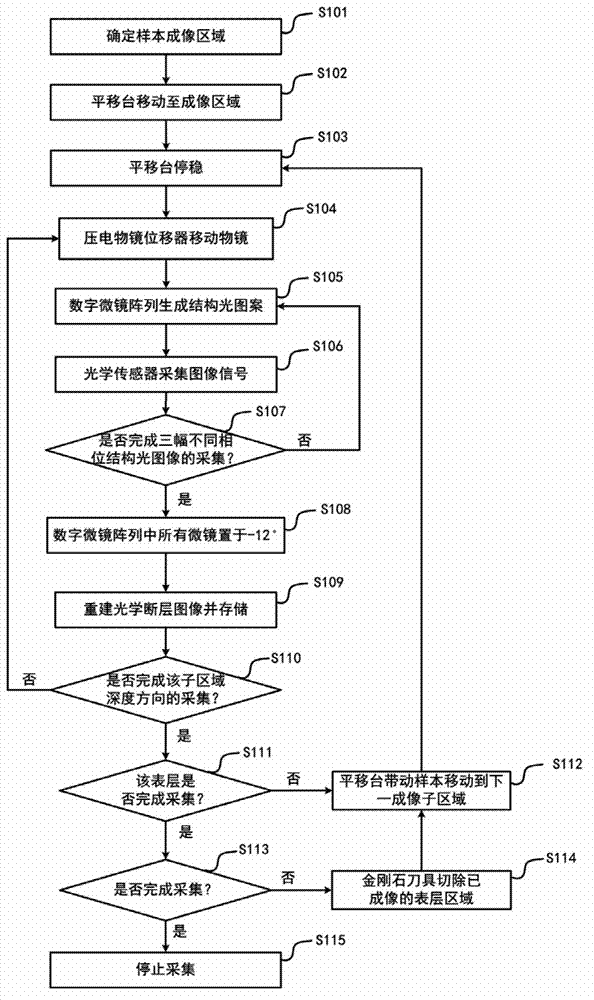
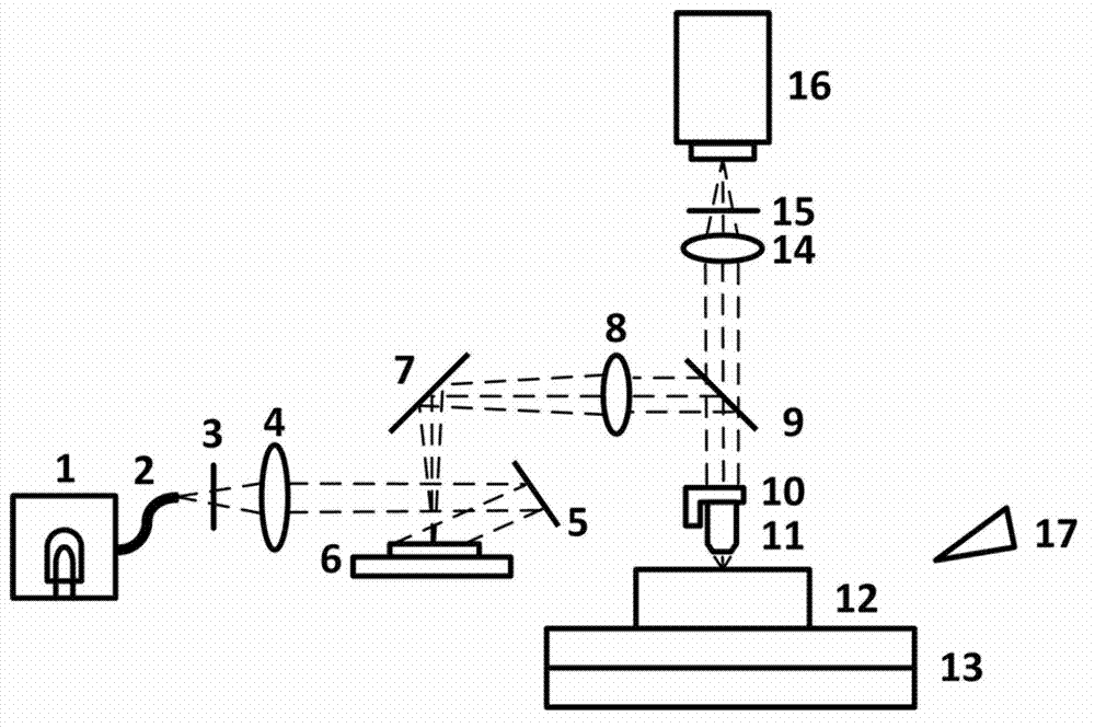
[0040] The light source is the X-cite 120 metal halide light source produced by Lumen Dynamics, which has its own output fiber. The specification of the digital micromirror array is 0.7 XGA, and the micromirror has two working states of +12° and -12°. The precision three-dimensional electric translation stage adopts the products of Aerotech Company of the United States. The precision three-dimensional electric translation stage is placed on the marble platform, and the positioning accuracy is sub-micron level to meet the needs of precision cutting and imaging. The diamond tool adopts the straight-edge diamond tool commonly used in electron microscope science, the blade angle is 35°, and the width is 3 mm. The tool and the tool holder are fixed on the steel tool holder.

[0041] The imaging objective lens is a 40x achromatic objective lens from Olympus, Japan. The piezoelectric displacement device uses the product of German PI company, and its positioning accuracy can reach 5 ...


PUM


Abstract

The invention relates to a method and system for rapidly three-dimensionally microimaging a large sample. The method comprises the following steps: 1, a sample is embedded in a sample block and is fixed on a precise three-dimensional electric translation platform; 2, a digital micro mirror array works in a binary modulation mode, and is used for carrying out binary modulation on illuminating light to form structure striations, a structured light microscope collects an image of the surface layer of the sample within a depth of 1-100micrometers; 3, completing the imaging of the inner surface layer of an imaging region, removing an imaged part of the surface layer of the sample block by using a diamond or hard alloy tool; and 4, repeating the steps 2 and 3 until a data acquiring task is completed. According to the invention, the digital micro mirror array works in the binary modulation mode, the imaging speed is effectively increased; and with an exposure synchronization method of the digital micro mirror array and a surface array camera, the sample can be irradiated by exciting light only when a surface array camera is exposed, the exposure quantity of the sample is further reduced, and the negative effects of a light bleaching effect to imaging is avoided.

Description

technical field [0001] The present invention relates to a microscopic imaging method and system, in particular to a microscopic optical imaging method and system based on structured light three-dimensional tomography, which are suitable for large samples. Background technique [0002] In the field of optical microscopy, people have been pursuing the acquisition of three-dimensional detail information of samples in a larger imaging area. However, this goal is restricted by three factors. First, the existence of scattered light will lead to the generation of background light. As a result, traditional microscope imaging will not only obtain information on the focal plane of the objective lens, but also superimpose blurred background from other areas. Obtain the three-dimensional tomographic image of the sample; the second is limited by the field of view and imaging speed of the microscopic objective lens, it usually takes dozens of days for microscopic imaging of centimeter-sca...

Claims


Application Information

Patent Timeline
IPC IPC(8): G02B21/00G02B21/06G02B21/36
Inventor 骆清铭龚辉许冬力李安安
Owner WUHAN OE BIO CO LTD
Learn More