
Soft X ray grazing incidence optical system based on double-energy-point multilayer membrane and application thereof

An optical system and multi-layer film technology, applied in the application of diffraction/refraction/reflection for processing, etc., can solve the problems of rising system cost, difficulty in operation and increase in experiment time, so as to reduce the difficulty of assembly and adjustment, reduce the cost of use, reduce The effect of cost of use

Inactive Publication Date: 2013-02-13
TONGJI UNIV
View PDF2 Cites 12 Cited by
  • Summary
  • Abstract
  • Description
  • Claims
  • Application Information

AI Technical Summary

Problems solved by technology

On the one hand, the construction or purchase of soft X-ray sources, vacuum target chambers, and vacuum electric shift stages has caused a sharp increase in system costs; on the other hand, the vacuum environment has also greatly increased the difficulty of operation and the experimental time

Method used


Image

  • Soft X ray grazing incidence optical system based on double-energy-point multilayer membrane and application thereof
  • Soft X ray grazing incidence optical system based on double-energy-point multilayer membrane and application thereof
  • Soft X ray grazing incidence optical system based on double-energy-point multilayer membrane and application thereof

Examples


Embodiment 1

[0030] This embodiment is applicable to the system setup and adjustment of the 4.75keV energy point KB microscope. KB microscope is mainly used for X-ray imaging diagnosis of high temperature and high density plasma in laser inertial confinement fusion.

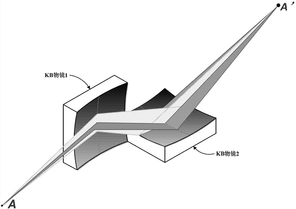
[0031] The schematic diagram of the optical path structure of this KB system is as follows: image 3 As shown, it consists of two spherical mirrors, KB objective lens 1 and KB objective lens 2, which are placed orthogonally in the meridional and sagittal directions respectively. The imaging formula is:

[0032] Meridian direction (corresponding to KB objective lens 1)

[0033] 1 u + 1 v + d = 2 R sin θ 1 - - - ( 1 ...

Embodiment 2

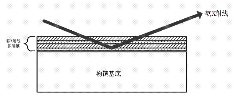
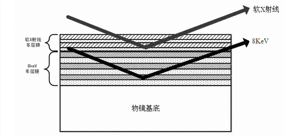
[0048] different from figure 1 As shown in the existing soft X-ray grazing incidence optical system, a kind of soft X-ray grazing incidence optical system based on dual energy point multilayer film of the present invention, such as figure 2 As shown, the optical system includes an objective lens base, and a dual-energy point multilayer film is coated on the objective lens base. The dual-energy point multilayer film is composed of an upper film system and a lower film system. The upper film system reflects soft X-rays at the working energy point. The lower film reflects X-rays at the 8keV energy point. Through multi-layer film design, the upper film system is aimed at the soft X-ray reflection of the actual working energy point in physical experiments; the lower film system is aimed at the X-ray reflection of the 8keV energy point, which is used for the soft X-ray grazing incidence optical system in the laboratory Objective lens assembly and system adjustment. The penetratio...


PUM


Abstract

The invention relates to a soft X ray grazing incidence optical system based on a double-energy-point multilayer membrane and an application thereof. The optical system comprises an objective lens, wherein the double-energy point multilayer membrane is plated on the objective lens, the double-energy-point multilayer membrane is composed of an upper side membrane system and a lower side membrane system, the upper side membrane system is used for reflecting aiming at working energy point soft X rays, and the lower side membrane system is used for reflecting aiming at 8 keV energy point soft X rays; and firstly the optimal object point of the 8 keV energy point is found through a Cu target X ray under a laboratory atmospheric environment, the optimal object point is the same as the optimal object point of the soft X ray grazing incidence optical system, and a strong laser device is switched and is used for an ICF (inertial confinement fusion) physical experiment on the actual soft X ray working energy point. Compared with the prior art, the soft X ray grazing incidence optical system has the advantages of being low in cost, simple in installation and adjustment, short in experiment time, capable of causing no additional error and adding no magnetron sputtering equipment, and the like.

Description

technical field [0001] The invention relates to a method for installing and adjusting a soft X-ray grazing incidence optical system, in particular to a method for installing and adjusting a soft X-ray grazing incidence optical system based on a dual-energy point multilayer film in an atmospheric environment, belonging to the field of imaging system installation and adjustment . Background technique [0002] The X-ray grazing incidence optical system is the key to high-temperature and high-density plasma diagnosis in the inertial confinement fusion (ICF) physical experiment of a strong laser device, mainly including KB / KBA and Wolter microscopic imaging system, and can also be used in energy spectrum diagnosis In order to improve the collection efficiency of X-rays as a light-gathering element. The effective field of view of this optical system is only a few hundred microns, which has high precision requirements for the assembly accuracy of the objective lens and system aimi...

Claims


Application Information

Patent Timeline
Patent Type & Authority Applications(China)
IPC IPC(8): G21K1/06
Inventor 伊圣振穆宝忠蒋励王占山王新
Owner TONGJI UNIV
Learn More