
Four-dimensional adjusting platform for optical detection

An optical detection and adjustment stage technology, applied in the direction of using optical devices, measuring devices, measuring instrument components, etc., can solve the problems of reduced data reliability, small size of multi-dimensional adjustment platform table, interference fringe jitter, etc. Effects of Stability and Adjustment Accuracy

Inactive Publication Date: 2013-02-20
XI'AN INST OF OPTICS & FINE MECHANICS - CHINESE ACAD OF SCI
View PDF8 Cites 11 Cited by
  • Summary
  • Abstract
  • Description
  • Claims
  • Application Information

AI Technical Summary

Problems solved by technology

[0002] In the process of optical inspection and assembly, various posture adjustment mechanisms are often used, such as translation tables, lifting tables, rotary tables, and angular displacement tables. At present, there are many companies dedicated to the research and development of such products in the domestic and foreign markets. These companies have many types of products, but most of their multi-dimensional adjustment platforms are small in size, which is difficult to meet the needs of medium-scale optical parts inspection and assembly.
For a long time, the multi-dimensional adjustment tables used in the inspection and adjustment of mesoscale optical parts are all made of single-degree-of-freedom adjustment mechanisms through simple splicing. Although this barely meets the needs of the work, it brings many new problems, such as: The interface forms of the degree of freedom adjustment mechanism are different, and it is difficult to match the interface when combined into a multi-degree-of-freedom adjustment mechanism; the stability of the multi-degree-of-freedom adjustment platform formed by simple splicing is poor, especially in the laser interferometry surface type detection due to the anti-interference of the adjustment mechanism Poor performance leads to interference fringe jitter, difficult data sampling, and reduced data reliability; at the same time, work efficiency is seriously affected

Method used


Image

  • Four-dimensional adjusting platform for optical detection
  • Four-dimensional adjusting platform for optical detection
  • Four-dimensional adjusting platform for optical detection

Examples


Embodiment Construction

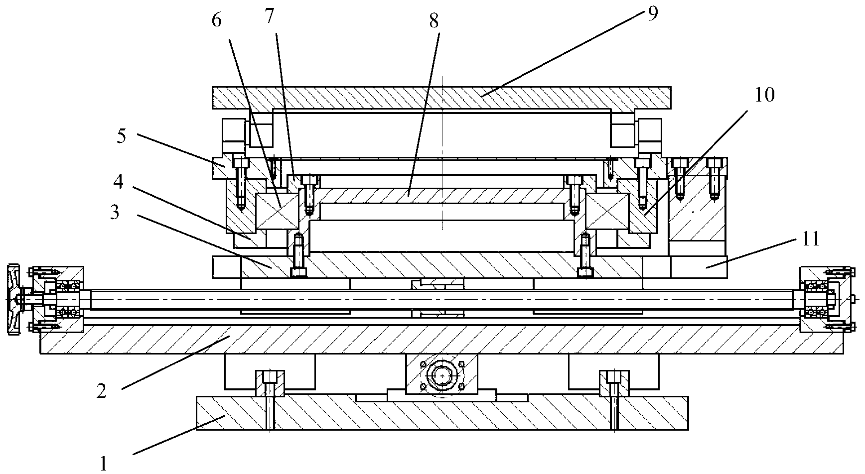
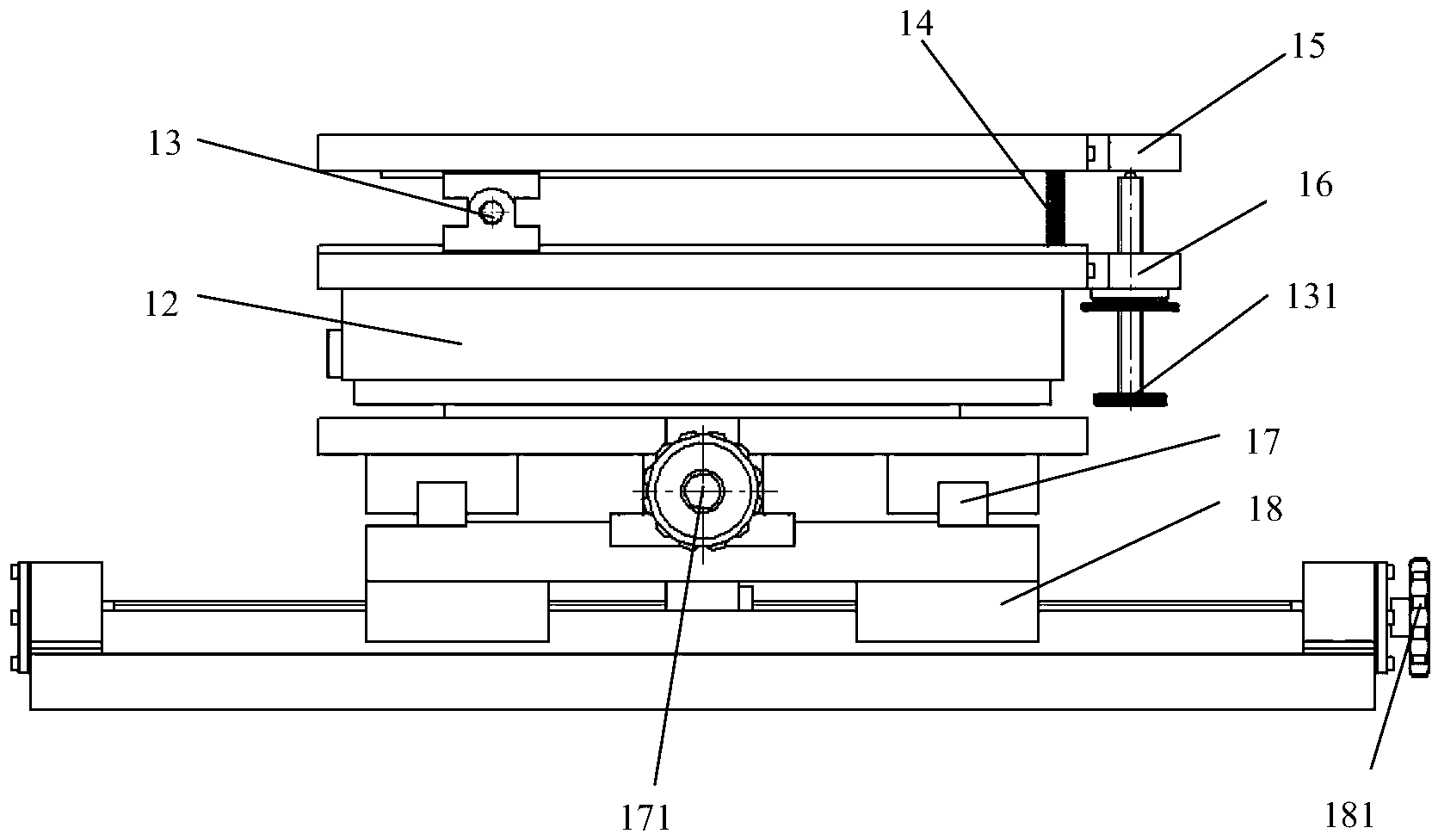
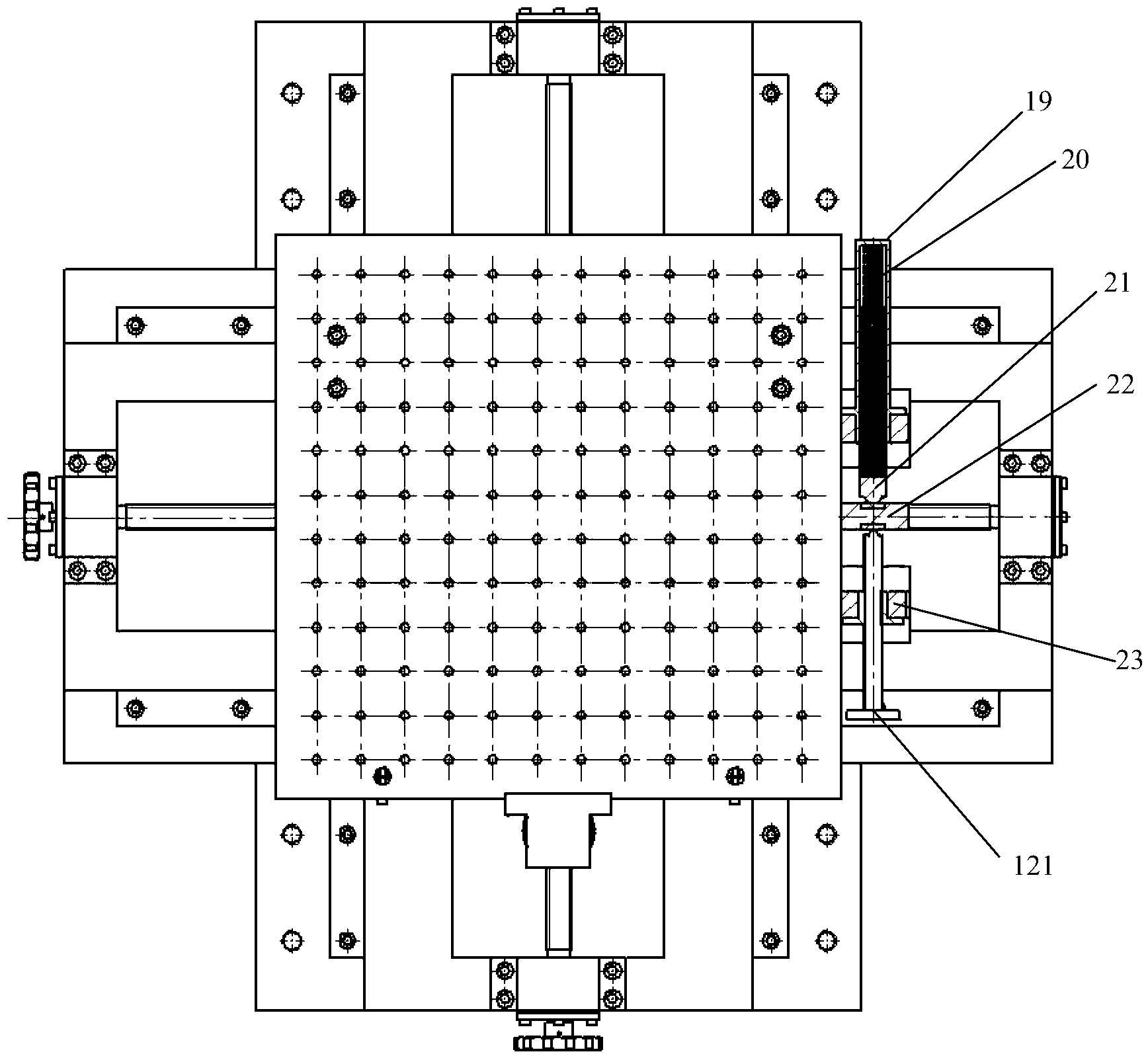
[0026] Such as Figure 1 to Figure 3 As shown, the spatial layout of the four-dimensional adjustment stage for optical detection can be divided into four layers from top to bottom, each of which undertakes different motion functions. The workbench and the pan / tilt are connected through the pitch joint to realize the adjustment of the pitch angle. The pitch joint is located at four-fifths of the total length of the workbench. It is always in close contact with the ball head of the adjusting screw; at the same time, there is a tension spring between the worktable and the cloud platform. The extension spring prevents virtual contact or overturning of the workbench even when it is used under extreme load conditions (the center of gravity of the load is seriously biased towards the end of the pitch joint). The pan-tilt and the lateral displacement platform are connected through a yaw joint, and the present invention preferably realizes the yaw movement through cross cylindrical ro...


PUM


Abstract

The invention provides a dour-dimensional adjusting platform for optical detection. The requirement for accurate multi-dimensional adjustment work is met. The platform comprises a base, a longitudinal placement platform, a transverse placement platform, a cloud deck seat, a cloud deck, a working platform, joints and corresponding adjusting mechanisms, wherein the base, the longitudinal placement platform, the transverse placement platform, the cloud deck seat, the cloud deck and the working platform are arranged sequentially from bottom to up, and the joints are in a pitching direction, a deflection direction, a horizontal transverse straight line direction and a horizontal longitudinal straight line direction respectively. The dour-dimensional adjusting platform is simple in structure and capable of achieving dour-dimensional adjusting and has high stability and adjusting accuracy.

Description

technical field [0001] The invention relates to a multi-dimensional adjustment platform for optical detection. Background technique [0002] In the process of optical inspection and assembly, various posture adjustment mechanisms are often used, such as translation tables, lifting tables, rotary tables, and angular displacement tables. At present, there are many companies dedicated to the research and development of such products in the domestic and foreign markets. These companies have many types of products, but most of their multi-dimensional adjustment platforms are small in size, which is difficult to meet the needs of medium-scale optical parts inspection and assembly. For a long time, the multi-dimensional adjustment tables used in the inspection and adjustment of mesoscale optical parts are all made of single-degree-of-freedom adjustment mechanisms through simple splicing. Although this barely meets the needs of the work, it brings many new problems, such as: The in...

Claims


Application Information

Patent Timeline
Patent Type & Authority Applications(China)
IPC IPC(8): G01D11/30G01B11/00
Inventor 王鹏李华杨宾宏
Owner XI'AN INST OF OPTICS & FINE MECHANICS - CHINESE ACAD OF SCI
Learn More