Method for determining matching relations among components in photoetching lighting system

A technology for lighting systems and matching relationships, applied in the field of determining matching relationships between components in lithography lighting systems

Active Publication Date: 2013-02-20
BEIJING INSTITUTE OF TECHNOLOGYGY
View PDF6 Cites 3 Cited by
  • Summary
  • Abstract
  • Description
  • Claims
  • Application Information

AI Technical Summary

Problems solved by technology

However, how to determine the matching relationship between the various parts in the design of the lithography lighting system is not given.

Method used


Image

  • Method for determining matching relations among components in photoetching lighting system
  • Method for determining matching relations among components in photoetching lighting system
  • Method for determining matching relations among components in photoetching lighting system

Examples


Embodiment

[0043] There is an existing lithography lighting system, and its design requirements are listed in Table 1 as follows:

[0044] Table 1: Lithography illumination system requirements

[0045] Illumination image square NA

0.1875

Lighting area size

104mm×42mm

[0046] In this embodiment, firstly, the magnification of the steering mirror is selected to be 1×. Then the condenser lens NA=0.1875, the illumination area of ​​the back focal plane of the condenser lens is 108mm×46mm, which is slightly larger than the mask illumination area, and at the same time, the partial coherence factor of the lithography illumination system σ=1.

[0047] According to the current processing situation of the microlens array, and according to the design method proposed in this patent, the specifications of the compound eye array are finally determined as shown in the following table:

[0048] Table 2: Specifications of Compound Eye Homogenizer

[0049]

[0050] Acco...


PUM

PropertyMeasurementUnit
lengthaaaaaaaaaa

Abstract

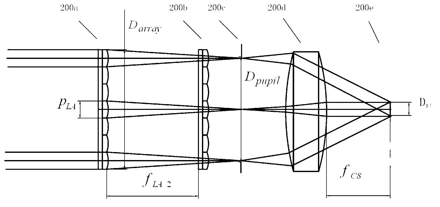
The invention provides a method for determining matching relations among components in a photoetching lighting system. The method can determine the matching relations of the components in the photoetching lighting system correctly and fast. The detailed process includes: determining magnification K of a relay lens; determining compound eye array parameters comprising a compound eye array micro lens aperture p LA, micro lens focal length f LA in the compound eye array and a compound eye array outer diameter D array; obtaining focal length f CS of a collecting lens and entrance pupil diameter D pupil of the collecting lens according to a kohler lighting basic principle; judging whether D pupil is larger than D array, on yes judgment, selecting a compound eye array again, otherwise, conducting light tracking according to a current determined parameter D pupil, adjusting a compound eye array standard and the D pupil till lighting evenness meets design objective requirements; and enabling the D pupil to be an outgoing beam of a beam shaping unit, determining the matching relations among a beam expanding lens, diffractive optical elements, a zoom lens and a cone lens according to an incident beam and the outgoing beam of the beam shaping unit so as to finish matching of the components in the photoetching lighting system.

Description

technical field [0001] The invention relates to a method for determining the matching relationship between components in a lithography illumination system, and belongs to the technical field of high-resolution lithography. Background technique [0002] Photolithography is a technology for manufacturing semiconductor devices, which uses optical methods to transfer the circuit pattern on the mask plate to the silicon wafer. Photolithography technology uses deep ultraviolet light sources, such as ultraviolet (UV), deep ultraviolet (DUV) and so on. A variety of semiconductor devices can be fabricated using photolithography, such as diodes, transistors, and VLSI. A typical lithography exposure system includes illumination system, mask, projection objective lens and silicon wafer. [0003] The lithography illumination system can achieve uniform illumination of the mask and produce various secondary illumination sources that match the entrance pupil of the objective lens, and its...

Claims


Application Information

Patent Timeline
Patent Type & Authority Applications(China)
IPC IPC(8): G03F7/20G02B27/09G02B27/42
Inventor 李艳秋魏立冬
Owner BEIJING INSTITUTE OF TECHNOLOGYGY
Why Eureka
Try Eureka