Depositing device

A technology of deposition device and fixing device, applied in gaseous chemical plating, coating, electrical components, etc., can solve the problems of easily containing impurities and low film quality, and achieve the effect of improving surface quality and reducing impurities

Active Publication Date: 2013-02-20
SHANGHAI HUAHONG GRACE SEMICON MFG CORP
View PDF3 Cites 11 Cited by
  • Summary
  • Abstract
  • Description
  • Claims
  • Application Information

AI Technical Summary

Problems solved by technology

[0005] However, the quality of the film formed by the existing vertical deposition furnace tube is still low, and it is easy to contain impurities

Method used


Image

  • Depositing device
  • Depositing device
  • Depositing device

Examples


no. 1 example

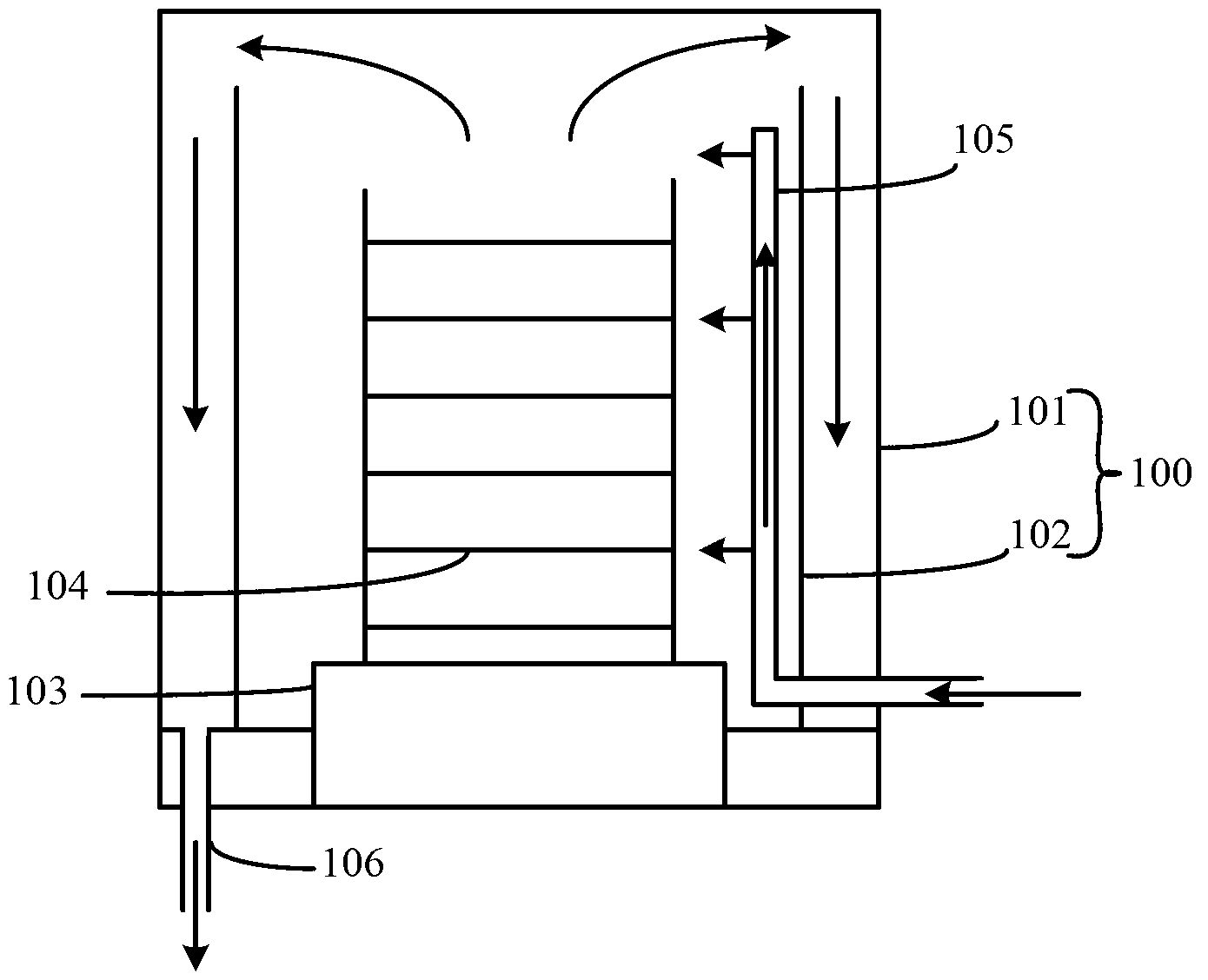
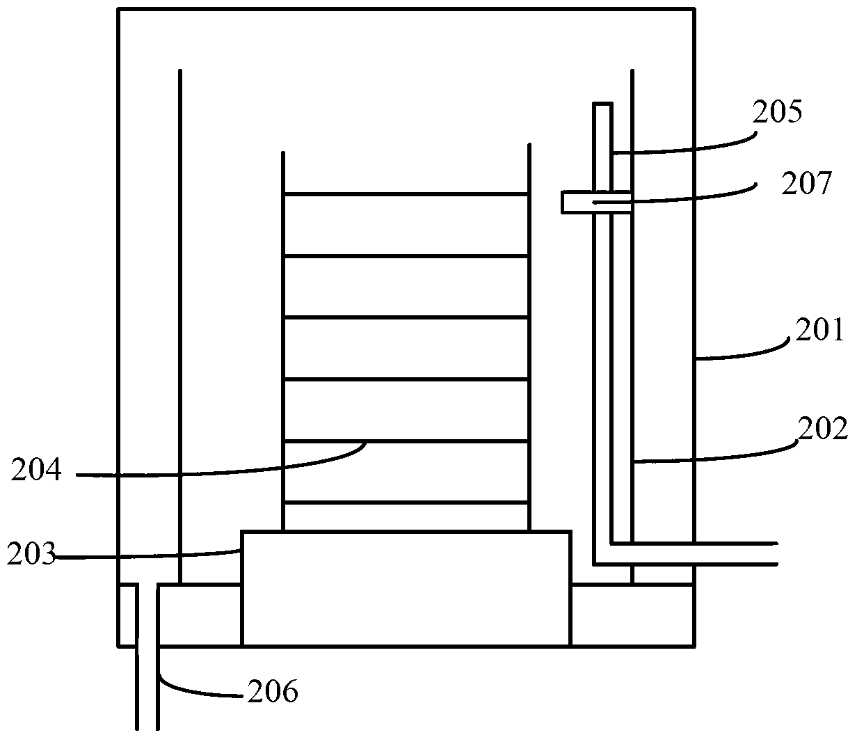
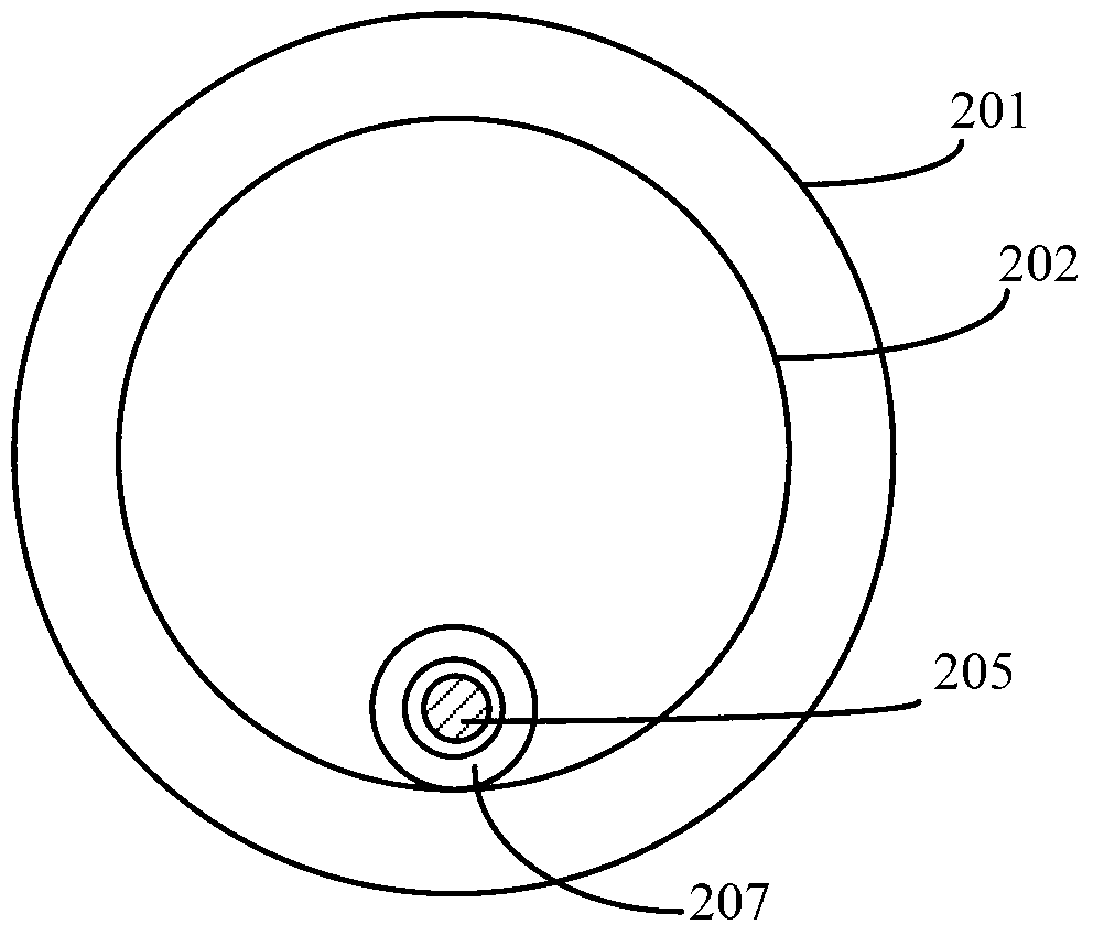
[0034] Please refer to figure 2 , figure 2 It is a schematic cross-sectional structure diagram of the deposition device described in the first embodiment of the present invention, including: an outer furnace tube 201; an inner furnace tube 202 located inside the outer furnace tube 201, the bottom of the inner furnace tube 202 is fixed to the outer furnace tube The bottom of the furnace tube 201, the top of the inner furnace tube 202 is open, and the top of the inner furnace tube 202 is not in contact with the top of the outer furnace tube 201; the base located at the inner bottom of the inner furnace tube 202 203; several overlapping crystal boats 204 fixed on the surface of the base 203; a gas supply pipeline 205 extending from the outside of the outer furnace tube 201 into the interior of the inner furnace tube 202, and the gas supply pipeline 205 is routed from the inner furnace tube 202 The bottom of the furnace tube 202 extends toward the top of the inner furnace tube ...

no. 2 example

[0051] Please refer to Figure 4 with Figure 5 , Figure 4 is a schematic cross-sectional structure diagram of the deposition device described in the second embodiment of the present invention, Figure 5 It is a top view structural diagram of the deposition device described in the second embodiment of the present invention, including: a closed outer furnace tube 301; an inner furnace tube 302 located inside the outer furnace tube 301, the bottom of the inner furnace tube 302 is fixed on the The bottom of the outer furnace tube 301, the top of the inner furnace tube 302 is an opening, and the top of the inner furnace tube 302 is not in contact with the top of the outer furnace tube 301; A base 303; a plurality of overlapping crystal boats 304 fixed on the surface of the base 303; a gas supply pipeline 305 extending from the outside of the outer furnace tube 301 into the interior of the inner furnace tube 302, and the gas supply pipeline 305 is from the The bottom of the inn...


PUM


Abstract

A depositing device comprises an outer furnace tube, an inner furnace tube located in the outer furnace tube, a base located at the bottom in the inner furnace tube, a plurality of overlapped boats fixed on the base surface, an air supply pipe extending into the inner furnace tube from the outside of the outer furnace tube, a fixing device fixedly arranged on the lateral wall of the inner furnace tube and an exhaust pipe located between the outer furnace tube and the inner furnace tube, wherein the bottom of the inner furnace tube is fixed at the bottom of the outer furnace tube, an opening is arranged at the top of the inner furnace tube, and the top of the inner furnace tube is not contacted with the top of the outer furnace tube; the air supply pipe extends from the bottom of the inner furnace tube to the top of the inner furnace tube; and the fixing device is used for fixing the air supply pipe extending from the bottom of the inner furnace tube to the top of the inner furnace tube. The depositing device can be prevented from toppling caused by too fast instantaneous velocity of air in the air supply pipe or cannot generate scraps caused by the fact that the air supply pipe collides with the lateral wall of the inner furnace tube or the boat, and accordingly formed films are good in quality.

Description

technical field [0001] The invention relates to the technical field of semiconductor manufacturing, in particular to a deposition device. Background technique [0002] Chemical vapor deposition (Chemical vapor deposition, referred to as CVD) is a process technology in which reactant substances undergo a chemical reaction under gaseous conditions to form a solid substance that is deposited on the surface of a heated solid substrate to obtain a solid thin film material. be realized. Specifically, the chemical vapor deposition device feeds the reaction gas into the chamber through the gas inlet device, and controls the reaction conditions such as the pressure and temperature of the chamber, so that the reaction gas reacts, thereby completing the deposition process steps. [0003] In the prior art, the vertical deposition furnace tube is a commonly used chemical vapor deposition device, such as figure 1 As shown, it includes: a chamber 100, the chamber 100 includes: an outer f...

Claims


Application Information

Patent Timeline
Patent Type & Authority Applications(China)
IPC IPC(8): H01L21/67C23C16/44
Inventor 王硕许忠义
Owner SHANGHAI HUAHONG GRACE SEMICON MFG CORP
Why Eureka
Try Eureka