Unlock instant, AI-driven research and patent intelligence for your innovation.

Clock synchronization device applicable to quantum communication system

A technology of clock synchronization and quantum communication, which is applied in the field of quantum communication optical fiber transmission, can solve the problems of inability to restore single-photon signals and synchronous optical signals, affecting security, accurate transmission of confidential information, and inability to ensure accurate separation of single-photon signals and synchronous optical signals, etc. problems, to achieve the effect of saving fiber resources

Inactive Publication Date: 2013-02-20
SHANGHAI LANGYAN OPTOELECTRONICS TECH
View PDF9 Cites 14 Cited by
  • Summary
  • Abstract
  • Description
  • Claims
  • Application Information

AI Technical Summary

Problems solved by technology

However, this method has a great waste of fiber resources, and due to the different transmission environments of single-photon signals and synchronous optical signals, there is a defect of relative phase jitter in the signal transmission process, which is harmful to systems with high repetition rates. deadly impact
In order to overcome the above defects, engineers and technicians try to use an optical fiber to transmit the synchronous optical signal in which the single photon signal of quantum communication is synchronized with the clock. The crosstalk to the single photon signal makes it impossible to restore the single photon signal and the synchronous optical signal at the receiving end; in the prior art, the single photon signal and the synchronous optical signal are simply coupled by wavelength division multiplexing. However, the accurate separation of the single photon signal and the synchronous optical signal cannot be guaranteed, which will cause a part of the synchronous optical signal to enter the single photon signal, so that the synchronous optical signal will cause a trigger signal to the single photon signal, resulting in a bit error, which affects safety, Accurate Transmission of Confidential Information

Method used


Image

  • Clock synchronization device applicable to quantum communication system

Examples


Embodiment

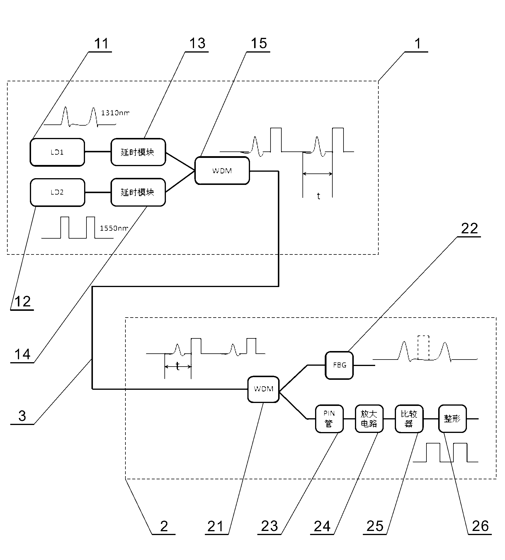
[0011] refer to figure 1 , first at the signal transmitting end 1, respectively set LD1 first laser pulse generator 11 to send a 1310nm optical pulse as a single photon signal, set LD2 second laser pulse generator 12 to send a 1550nm optical pulse as a synchronous optical signal , the phase of the single photon signal is controlled by the first delay module 13, and the phase of the synchronous optical signal is controlled by the second delay module 14, so that the single photon signal and the two optical pulses of the synchronous optical signal have a certain phase difference, and The two optical pulse signals are respectively sent to the first wavelength division multiplexer 15 of WDM1, and after being coupled by the first wavelength division multiplexer 15 of WDM1, they are input to the same transmission optical fiber 3 and transmitted to the signal receiving end 2;

[0012] Secondly, at the signal receiving end 2, the coupling signal is received by the WDM2 second wavelengt...


PUM


Abstract

The invention discloses a clock synchronization device applicable to a quantum communication system. The device comprises a signal sending end, a signal receiving end and a transmission fiber, wherein the signal sending end is provided with first and second laser pulse generators, first and second delay modules, and a first wavelength division multiplexer, wherein the signal receiving end is provided with a second wavelength division multiplexer, a Bragg grating and a PIN (positive-intrinsic negative) diode; and the transmission fiber is connected to an output end of the first wavelength division multiplexer and an input end of the second wavelength division multiplexer. According to the invention, by adopting the signal time-staggered transmission and wavelength division multiplexing technology, the phase difference between a single photon signal and a synchronous optical signal is controlled by the delay modules, the single photon signal and the synchronous optical signal are coupled to a same fiber for transmission, thereby saving the fiber resource, and ensuring that the synchronous optical signal does not trigger the signal photon signal and result in crosstalk.

Description

technical field [0001] The invention relates to the technical field of quantum communication optical fiber transmission, in particular to a clock synchronization device suitable for quantum communication systems. Background technique [0002] Quantum communication technology is a new type of communication means, especially in the field of confidentiality and security of communication. Quantum communication uses single photon as the information carrier, and realizes the safe and confidential transmission of information between two users through its quantum characteristics. In the specific implementation process of the quantum communication system, the clock synchronization technology is one of the key technologies of the system, which determines the correctness of the key screening and the consistency of the codebooks of both parties during the quantum key distribution. [0003] In the prior art, two optical fibers are usually used in the quantum communication system to resp...

Claims


Application Information

Patent Timeline
IPC IPC(8): H04J3/06H04J14/02
Inventor 陈杰李军曾和平
Owner SHANGHAI LANGYAN OPTOELECTRONICS TECH
Features
  • R&D
  • Intellectual Property
  • Life Sciences
  • Materials
  • Tech Scout
  • Unparalleled Data Quality
  • Higher Quality Content
  • 60% Fewer Hallucinations
Learn More