Interferometer system based secondary surveillance radar response signal direction-finding method

A secondary radar and response signal technology, which is applied to the orientation device, instrument, measuring device, etc. of direction determination, can solve the problems of lack of air surveillance means and equipment, infinite direction measurement error, limited coverage, etc., and achieve high precision The effect of passive azimuth measurement, low cost, and large instantaneous direction finding range

Active Publication Date: 2013-02-27
SICHUAN JIUZHOU ELECTRIC GROUP
View PDF2 Cites 29 Cited by
  • Summary
  • Abstract
  • Description
  • Claims
  • Application Information

AI Technical Summary

Problems solved by technology

But there are also shortcomings: In order to obtain high angle measurement accuracy, the secondary radar ground interrogation antenna adopts a narrow beam design, and the 3dB beam width in the azimuth plane generally does not exceed 10 degrees, and wide airspace coverage is achieved through mechanical scanning; the ground interrogation machine needs to actively transmit inquiries Signal, so the system is complex, power consumption is high, and the cost is high
Secondary radar ground interrogators are mainly deployed at airports and some important air route nodes. In the areas outside their coverage, there is still a lack of effective means and equipment for air surveillance
The phase interferometer direction finding technology also has a big defect: the direction finding error is greater in the area closer to the antenna baseline direction, and the direction finding error is infinite in the antenna baseline direction so that the direction finding cannot be done
[0006]Secondary radar ground interrogation system has high power consumption, high cost and limited coverage

Method used


Image

  • Interferometer system based secondary surveillance radar response signal direction-finding method
  • Interferometer system based secondary surveillance radar response signal direction-finding method
  • Interferometer system based secondary surveillance radar response signal direction-finding method

Examples


Embodiment Construction

[0030] All features disclosed in this specification, or steps in all methods or processes disclosed, may be combined in any manner, except for mutually exclusive features and / or steps.

[0031] Any feature disclosed in this specification (including any appended claims, abstract and drawings), unless expressly stated otherwise, may be replaced by alternative features which are equivalent or serve a similar purpose. That is, unless expressly stated otherwise, each feature is one example only of a series of equivalent or similar features.

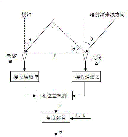
[0032] For the direction finding principle of one-dimensional linear array single baseline phase interferometer see figure 1 , let the baseline size be D, and the incident angle of the radiation source be θ (the included angle with the visual axis). It can be known from the geometric relationship that there is a wave path difference Δ when the radiation source signal enters the two receiving channels L :

[0033] ...


PUM


Abstract

The invention discloses an interferometer system based secondary surveillance radar response signal direction-finding method, which relates to the technical field of radio monitoring. The method comprises the following steps that: a 4-array-element direction-finding antenna array with a receiving sidelobe suppression antenna unit receives secondary radar response signals, and four receiving channels respectively carry out digital measuring on frequency, amplitude and phase parameters; then, an operation of controlling the receiving sidelobe suppression of an instantaneous direction-finding range and an operation of exhaustion based long-short baseline resolving phase ambiguity are performed; and finally, the orientation resolving is completed through phase orientation mapping. A secondary radar response signal direction-finding system using the method disclosed by the invention has the advantages of high direction-finding precision, rapid direction-finding speed, large instantaneous direction-finding range, low power consumption, low cost, capability of carrying out passive direction-finding, and the like, and has a good application prospect and economic benefits in promoting the air surveillance range in the field of air management and monitoring.

Description

technical field [0001] The present invention relates to the technical field of radio monitoring, in particular to a direction finding method for air traffic control secondary radar (hereinafter referred to as secondary radar) response signal based on an interferometer system. Background technique [0002] Secondary radar is composed of ground interrogator and airborne transponder. Secondary radar system is an important means to realize air traffic control. The ground interrogator uses the 1030MHz signal to make directional inquiries to the airborne transponder, including A and C modes. After the airborne transponder receives an effective interrogation signal, it responds omnidirectionally with the corresponding mode 1090MHz signal, and the ground interrogator detects the corresponding response signal. The detection, positioning and information acquisition of the carrier aircraft are realized. At the same time, the airborne transponder can receive the interrogation signals i...

Claims


Application Information

Patent Timeline
Patent Type & Authority Applications(China)
IPC IPC(8): G01S3/46
Inventor 先登飞颜伏虎张珂彭琪
Owner SICHUAN JIUZHOU ELECTRIC GROUP
Why Eureka
Try Eureka