
Optical beam splitter performing separation based on coupled mode

A technology of coupling mode and optical beam splitter, which is applied in the direction of light guide, optics, instrument, etc., can solve the problems of limited variation range of beam splitting ratio and large insertion loss, and achieve large process tolerance, low insertion loss and wide wavelength range Effect

Inactive Publication Date: 2013-02-27
INST OF SEMICONDUCTORS - CHINESE ACAD OF SCI
View PDF3 Cites 7 Cited by
  • Summary
  • Abstract
  • Description
  • Claims
  • Application Information

AI Technical Summary

Problems solved by technology

Based on the self-image principle of multimode interference, the multimode interference beam splitter is mainly used for uniform light splitting, so the range of the beam splitting ratio is very limited; the two output waveguides of the 2×2 multimode interference beam splitter are connected to a certain There is an asymmetric structure between the input waveguides, in order to achieve uniform light splitting, the radiation mode will be excited, so the insertion loss is relatively large

Method used


Image

  • Optical beam splitter performing separation based on coupled mode
  • Optical beam splitter performing separation based on coupled mode
  • Optical beam splitter performing separation based on coupled mode

Examples


Embodiment 1

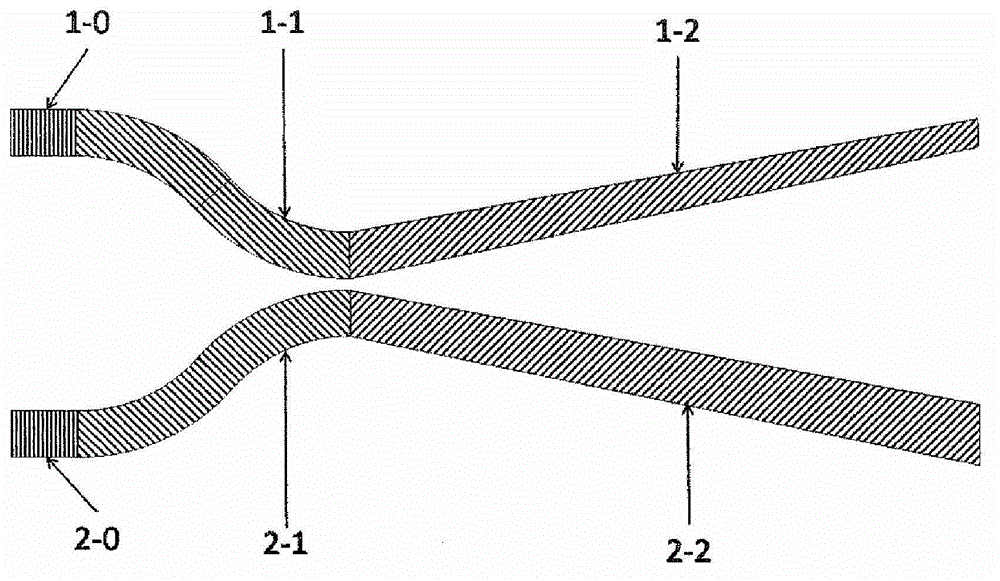
[0038] This embodiment is an optical beam splitter with a beam splitting ratio of 0.5 / 0.5 designed according to the structure shown in FIG. . Both the input end 1-0 of the first waveguide 1 and the input end 2-0 of the second waveguide 2 have a ridge width of 500nm. In the coupling mode excitation region 1-1 or 2-1, the distance between the two waveguides decreases in an arc-shaped manner. Small, to about 100nm or less, and the ridge width remains unchanged; in the coupling mode separation region 1-2 or 2-2, the distance between the two waveguides increases linearly, and the maximum distance is greater than 700nm, while the coupling mode separation region 1 of the first waveguide 1 The -2 ridge width decreases linearly to less than 450nm, while the coupled mode separation region 2-2 ridge width of the second waveguide 2 linearly increases to greater than 550nm.

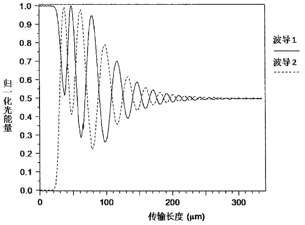
[0039] Figure 2(a) is the simulation result of the beam propagation method of the above embodiment, the wavelength...

Embodiment 2

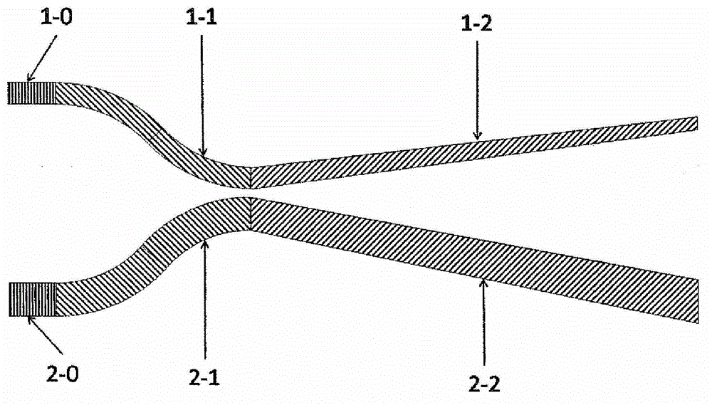
[0041] The present embodiment is an optical beam splitter whose beam splitting ratio is 0.9 / 0.1 according to the structural design shown in Fig. The ridge width of the input terminal 2-0 is 532nm, and other parameters are the same as those in Embodiment 1.

[0042] Fig. 2(b) is the simulation result of the beam propagation method of the above embodiment. It can also be seen that as the transmission distance increases, the beam splitting ratio tends to be stable around 0.9 / 0.1, and there is no obvious insertion loss.


PUM


Abstract

The invention discloses an optical beam splitter performing separation based on a coupled mode. The optical beam splitter comprises a first waveguide (1) and a second waveguide (2) which are adjacent and can achieve optical beam splitting in a 2*2 mode. A distance between the two waveguides is first decreased gradually to form a coupled-mode excitation region under the condition that the size of the waveguides does not change, and then the distance between the two waveguides is increased gradually to form a coupled-mode separation region under the condition that the size of the waveguides changes towards the reverse direction. By adjusting structures of the two waveguides in the coupled-mode excitation region, the optical beam splitter can achieve various beam splitting ratios. Due to the fact that the separation in the coupled mode is achieved based on changes of a heat-insulating mode, the optical beam splitter has the advantages of being low in insertion loss, wide in wavelength range, large in process tolerance and the like.

Description

technical field [0001] The invention relates to an optical beam splitter applied in the fields of optical communication, optical interconnection, optical computing, integrated optics, optical sensing, etc., in particular to an optical beam splitter which can realize arbitrary splitting ratio, low insertion loss, wide wavelength range and A 2×2 optical beam splitter based on coupling mode separation with large process tolerance. Background technique [0002] Optical beam splitter is an important basic optical component, which is widely used in optical communication, optical interconnection, optical computing, integrated optics, optical sensing and other fields. Currently commonly used 2×2 beam splitters mainly include directional coupling beam splitters and multimode interference beam splitters. increasingly prominent. The principle of the directional coupling beam splitter is based on the interference of the coupling mode. Since the coupling mode is very sensitive to the w...

Claims


Application Information

Patent Timeline
Patent Type & Authority Applications(China)
IPC IPC(8): G02B6/125
Inventor 邢界江李智勇肖希储涛俞育德余金中
Owner INST OF SEMICONDUCTORS - CHINESE ACAD OF SCI
Learn More