High-speed railway based aerodynamic aerotrain with simulated wings on chassis of aerotrain body

An aerodynamic levitation, high-speed railway technology, applied in the direction of railway car body, railway car body parts, air resistance reduction technology, etc., can solve the problems of waste of resources, inability of trains to change tracks, serious safety accidents of maglev trains, etc., to reduce pressure , the effect of stable train running and simple structure

Active Publication Date: 2013-03-06
BEIHANG UNIV
View PDF6 Cites 18 Cited by
  • Summary
  • Abstract
  • Description
  • Claims
  • Application Information

AI Technical Summary

Problems solved by technology

[0002] At present, the known means of speeding up trains based on high-speed railways is to use magnetic levitation to reduce the friction of the wheels on the rails. However, the disadvantages of the magnetic levitation method are: 1. The train cannot change tracks, unlike trains that run on conventional railways. Turnouts go from one track to another; one track can only accommodate one train running back and forth, resulting in a waste of resour

Method used


Image

  • High-speed railway based aerodynamic aerotrain with simulated wings on chassis of aerotrain body
  • High-speed railway based aerodynamic aerotrain with simulated wings on chassis of aerotrain body
  • High-speed railway based aerodynamic aerotrain with simulated wings on chassis of aerotrain body

Examples


Embodiment 1

[0049] See Figure 4 and Figure 5 , the wing-like structure is mainly composed of a fixed base 4 of cuboid structure and a horizontal wing 1 fixed thereon; wherein, one side of the fixed base is connected with the horizontal wing, and the other side is installed on the side of the locomotive or carriage, fixed The horizontal length of the base is 1 meter, the width is 30 cm, the thickness of the fixed base is 65 mm, and the horizontal wing and the fixed base form a 90-degree right angle.

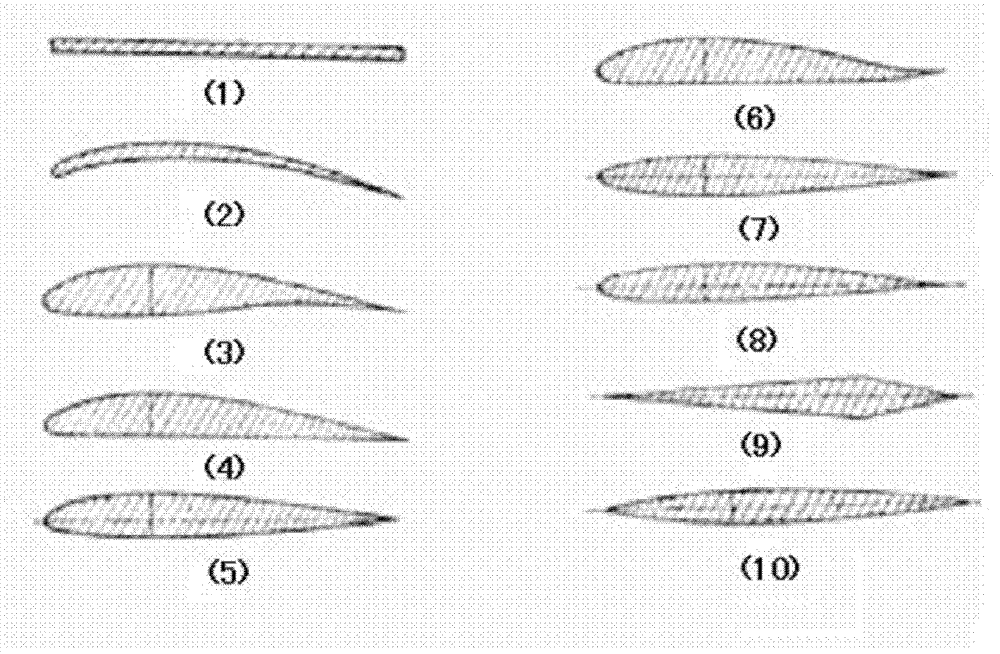
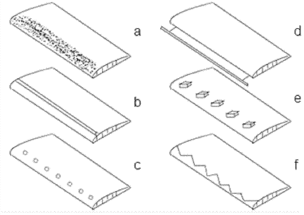
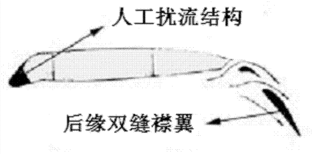
[0050] Described horizontal wing adopts flat wing, and the section of its flat wing is as follows figure 1 As shown in (1), it is streamlined as a whole, with an angle of attack, a leading edge sweep angle and a trailing edge sweep angle; the artificial spoiler structure 2 added near the leading edge part of the upper surface of the horizontal wing is A raised spoiler bar (such as figure 2 Shown in b); The trailing edge of the horizontal wing is equipped with a trailing edge double-sli...

Embodiment 2

[0063] See Figure 4 and Figure 5 , the wing-like structure is mainly composed of a fixed base 4 of cuboid structure and a horizontal wing 1 fixed thereon; wherein, one side of the fixed base is connected with the horizontal wing, and the other side is installed on the side of the locomotive or carriage, fixed The horizontal length of the base is 1 meter, the width is 30 cm, the thickness of the fixed base is 60 mm, and the horizontal wing and the fixed base form a 90-degree right angle.

[0064] Described horizontal wing adopts flat wing, and the section of its flat wing is as follows figure 1 Shown in (1), the artificial spoiler structure added near the leading edge part of the upper surface of the horizontal wing is a zigzag protruding spoiler (such as figure 2 shown in f).

[0065] The area of ​​described horizontal wing is 2.25 square meters, and this moment root tip ratio is 1, and the length of horizontal wing is 225 centimetres, and leading edge sweep angle is 0 ...

Embodiment 3

[0077] See Figure 4 and Figure 5 , the wing-like structure is mainly composed of a fixed base 4 of cuboid structure and a horizontal wing 1 fixed thereon; wherein, one side of the fixed base is connected with the horizontal wing, and the other side is installed on the side of the locomotive or carriage, fixed The horizontal length of the base is 1 meter, the width is 30 cm, the thickness of the fixed base is 60 mm, and the horizontal wing and the fixed base form a 90-degree right angle.

[0078] Described horizontal wing adopts flat wing, and the section of its flat wing is as follows figure 1 Shown in (1), the artificial flow disturbance structure added near the leading edge part of the upper surface of the horizontal wing is to add an elastic flow-around band (such as figure 2 shown in d).

[0079] The area of ​​described horizontal wing is 1.125 square meters, and this moment root tip ratio is 0.3, and the length of horizontal wing is 150 centimetres, and leading edg...


PUM

PropertyMeasurementUnit
Areaaaaaaaaaaa
Areaaaaaaaaaaa
Areaaaaaaaaaaa

Abstract

The invention relates to locomotives and carriages in railway systems, in particular to a high-speed railway based aerodynamic aerotrain with simulated wings on a chassis of an aerotrain body. Simulated wings in airplane wing simulated structure are symmetrically mounted on the left side and the right side of each carriage and the left side and right side of the chassis of a locomotive. In order to achieve better effects, enable the aerotrain to run more stably and safely and prevent the simulated wings from external wind direction influences, wind shields are arranged on two sides of a rail and above the wings. By the aid of the simulated wings mounted on the aerotrain, uplifting force is generated under the action of airflow in relative movement to the aerotrain, raising force can be provided for the aerotrain in high-speed running, and accordingly pressure applied to rails by the aerotrain is reduced, and extra energy consumption and pollution are avoided since the force is generated aerodynamically. Further, the simulated wings are simple in structure.

Description

technical field [0001] The present invention relates to locomotives and carriages in the railway system, and in particular to the use of aerodynamics to generate a certain degree of air suspension force for high-speed trains through the imitation wing structure imitating the wing structure of an airplane installed on the train A high-speed rail-based car-body chassis with aerodynamically suspended trains that resemble wings. Background technique [0002] At present, the known means of speeding up trains based on high-speed railways is to use magnetic levitation to reduce the friction of the wheels on the rails. However, the disadvantages of the magnetic levitation method are: 1. The train cannot change tracks, unlike trains that run on conventional railways. Turnouts go from one track to another; one track can only accommodate one train running back and forth, resulting in a waste of resources. 2. Since the maglev system relies on electromagnetic force for levitation, guida...

Claims


Application Information

Patent Timeline
IPC IPC(8): B61D17/02
CPCY02T30/32Y02T30/00
Inventor 江雷查金龙刘流马洋刘克松
Owner BEIHANG UNIV
Why Eureka
Try Eureka