
Visual detection method of longitudinal tear of conveying belt

A technology of longitudinal tearing and visual inspection, applied in conveyor objects, conveyor control devices, transportation and packaging, etc., can solve problems in image quality and real-time performance, cannot adapt to long-term real-time applications, ultrasonic testing equipment Too many problems, to achieve the effect of easy post-processing, fast response time and reliable performance

Active Publication Date: 2014-07-30
TAIYUAN UNIV OF TECH +2
View PDF8 Cites 4 Cited by
  • Summary
  • Abstract
  • Description
  • Claims
  • Application Information

AI Technical Summary

Problems solved by technology

[0003] At present, the detection of longitudinal tearing accidents of conveyor belts is divided into two types: contact detection and non-contact detection methods. There are too many devices, the effect is poor in engineering applications, and the value of sensor coil detection is very small in the application of belt conveyor transportation systems in my country. Ordinary visual detection has problems in light source, energy consumption, image quality and real-time performance, so it cannot adapt long time real-time application

Method used


Image

  • Visual detection method of longitudinal tear of conveying belt
  • Visual detection method of longitudinal tear of conveying belt
  • Visual detection method of longitudinal tear of conveying belt

Examples


Embodiment approach 1

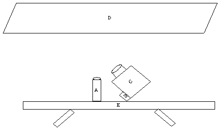
[0020] figure 1 It is an instrument diagram showing the visual detection method of longitudinal tearing of conveyor belt based on infrared CCD camera, and the instrument is installed according to this diagram.

[0021] Adjust the focal length of the infrared CCD camera so that the captured pictures can only be captured and can only capture the complete conveyor belt width. Program the single-chip microcomputer to realize the control of the infrared CCD camera's timing and triggering photography methods, and timing photography The time interval is 5 minutes to prevent the failure of the pyroelectric detector and cause missed judgments. The triggering of the photo is when the pyroelectric detector senses a rapid temperature change on the conveyor belt and generates a transient voltage. The transient voltage triggers the single-chip microcomputer. The single-chip microcomputer Trigger the infrared CCD camera switch, and the infrared CCD camera takes pictures.

[0022] Image proc...

Embodiment approach 2

[0029] The time interval for taking pictures at regular intervals is 4 minutes, and the others are the same as in Embodiment 1.

Embodiment approach 3

[0031] The time interval for taking pictures at regular intervals is 6 minutes, and the others are the same as in Embodiment 1.


PUM


Abstract

The invention relates to a visual detection method of longitudinal tear of a conveying belt, which belongs to the technical field of on-line monitoring of coal mine automation. The visual detection method is characterized in that in the condition of dim light or no light, a pyroelectric detector is used for detecting the temperature variation of the conveying belt due to the longitudinal tear, an infrared CCD (Charge-coupled Device) camera is controlled to take a photo, an obtained image is processed, and then an accident of the conveying belt can be accurately judged. According to the visual detection method, the simultaneous working mode of timing photo taking and triggering photo taking is adopted, omitted judgment caused by failure of the pyroelectric detector is prevented, and great energy of the infrared CCD camera, which is consumed by continuously taking photos for a long time, is saved. Additionally, negative effects that the service life of the infrared CCD camera is shortened and the working efficiency is reduced are avoided, wherein the negative effects are caused by the fact that the infrared CCD camera is continuously operated for a long time. A sharp image can be obtained by the infrared CCD camera when the conveying belt is moved at high speed, the obtained image is a grayscale image and is easily processed at a later period, and the position and the degree of the longitudinal tear can be visually reflected through finally processed information. The visual detection method has the advantages of high precision and reliable performance.

Description

technical field [0001] The invention discloses a visual detection method for longitudinal tearing of a conveyor belt, which belongs to the technical field of automatic online monitoring of coal mines. Once the longitudinal tear of the conveyor belt occurs, the pyroelectric detector quickly captures a large amount of heat generated due to the tear or deviation, controls the infrared CCD (Change-Coupled Device) camera to turn on and collects fixed-point images of the conveyor belt, and the image The information is transmitted to the computer, and through image processing, the technical solution for accurately judging the fault of the conveyor belt. Background technique [0002] Belt conveyors are widely used in mining, metallurgy, electric power and other industries due to their advantages such as safe and reliable operation and strong adaptability. As an important part of the conveyor, the conveyor belt accounts for about 40% of the entire conveyor cost. However, due to the...

Claims


Application Information

Patent Timeline
Patent Type & Authority Patents(China)
IPC IPC(8): B65G43/02G01N21/89
Inventor 乔铁柱赵弼龙靳宝全王峰马福昌张雪英满壮陈昕郑洪强
Owner TAIYUAN UNIV OF TECH
Learn More