True triaxial test ultrasonic wave and acoustic emission testing system and testing method thereof

A test system and test method technology, applied in the direction of applying stable tension/pressure to test the strength of materials, measuring devices, instruments, etc., can solve the problem that the nature and size of the acoustic emission source cannot be given, ultrasonic waves cannot propagate, and coupling is not achieved Test and other issues to avoid adverse effects, ensure normal transmission and reception, and protect the transducer

Inactive Publication Date: 2013-03-06
CHANGJIANG RIVER SCI RES INST CHANGJIANG WATER RESOURCES COMMISSION
View PDF4 Cites 31 Cited by
  • Summary
  • Abstract
  • Description
  • Claims
  • Application Information

AI Technical Summary

Problems solved by technology

Second, because different media have different absorption capabilities for ultrasonic waves, gas has a strong ability to absorb ultrasonic waves, ultrasonic waves can hardly propagate in gas, and solids have very weak absorption capabilities.
But so far, most of them are used alone. Even if they are used together, they only use two systems for testing separately, that is, one rock block is used for ultrasonic testing, and the other rock block is used for acoustic emission testing, and no real coupling test has been achieved. , and it is only used in conventional uniaxial tests, but no related reports have been seen in triaxial and true triaxial tests
In addition, acoustic emission detection is mainly used for rock materials. During the test process, the real-time or continuous information of defects changing with external variables such as load and time. At the same time, it can only give the location, activity and intensity of the acoustic emission source. The nature and size of the defect in the acoustic emission source cannot be given, and it still needs to rely on other non-destructive testing methods for re-inspection

Method used


Image

  • True triaxial test ultrasonic wave and acoustic emission testing system and testing method thereof
  • True triaxial test ultrasonic wave and acoustic emission testing system and testing method thereof

Examples


Embodiment Construction

[0027] Below in conjunction with accompanying drawing and embodiment the present invention is described in further detail:

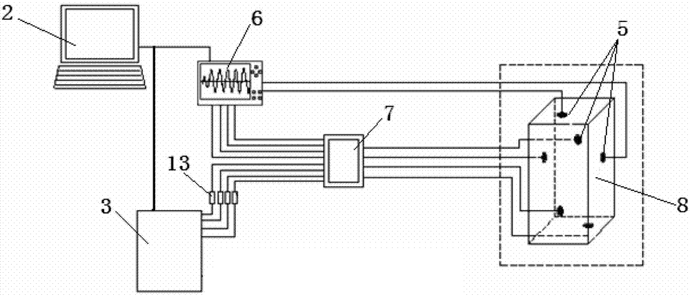
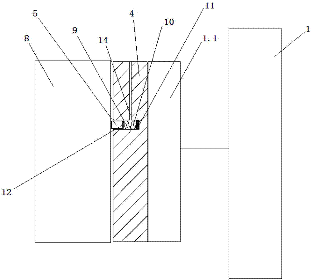
[0028] Such as figure 1 and 2The shown true triaxial test ultrasonic and acoustic emission testing system includes true triaxial test device 1, computer 2, acoustic emission instrument 3, ultrasonic and acoustic emission coupling test transducer 5, multi-channel ultrasonic flaw detector 6 and signal shunt 7, wherein, the true triaxial test device 1 has six pressure units 1.1, each surface pressure unit 1.1 and the corresponding surface of the rock block 8 is provided with an ultrasonic and acoustic emission coupling test transducer 5, at least one The communication end of the ultrasonic and acoustic emission coupling test transducer 5 is connected to the signal output end of the multi-channel ultrasonic flaw detector 6, and the communication ends of the rest of the ultrasonic and acoustic emission coupling test transducer 5 are respectively connected to...


PUM

PropertyMeasurementUnit
electrical bandwidthaaaaaaaaaa
Resonant frequencyaaaaaaaaaa
Sensitivityaaaaaaaaaa

Abstract

The present invention discloses a true triaxial test ultrasonic wave and acoustic emission testing system. According to the present invention, a true triaxial test apparatus has six sides of pressurization units, wherein ultrasonic wave and acoustic emission coupling test transducers are arranged between every side of the pressurization unit and corresponding surfaces of rock, a communication terminal of at least one ultrasonic wave and acoustic emission coupling test transducer is connected with a signal output terminal of a multi-channel ultrasonic wave defect detector, communication terminals of other ultrasonic wave and acoustic emission coupling test transducers are respectively connected with a signal input terminal of the multi-channel ultrasonic wave defect detector and a signal receiving terminal of an acoustic emission instrument through signal shunts, and the acoustic emission instrument and the multi-channel ultrasonic wave defect detector are connected with a computer. With the present invention, an ultrasonic wave test and an acoustic emission test can be performed on the same rock, completely comprehensive data information can be provided for understanding of deformation and breaking law, and mechanics mechanism of the rock, and adverse affects on test results by difference of different blocks can be avoided.

Description

technical field [0001] The invention relates to the technical field of rock failure tests, in particular to a true triaxial test ultrasonic and acoustic emission test system and test method. technical background [0002] Acoustic emission is an instantaneous elastic wave generated by the rapid release of energy from a local stress concentration source in a material. Acoustic emission is a common physical phenomenon. The frequency range of acoustic emission signals of various materials is very wide, ranging from subsonic frequencies of several Hz, 20Hz ~ 20K Hz sound frequency to several MHz ultrasonic frequency; the amplitude of the acoustic emission signal also varies greatly, from 10m microscopic dislocation movement to 1m magnitude seismic wave. If the strain energy released by acoustic emission is large enough, it can produce sound audible to the human ear. Acoustic emission occurs when most materials are deformed and broken, but the strength of the acoustic emission si...

Claims


Application Information

Patent Timeline
Patent Type & Authority Applications(China)
IPC IPC(8): G01N3/08G01N3/06
Inventor 黄书岭丁秀丽邬爱清李维树段海波周火明钟作武卢波董志宏张雨霆张练吴勇进付敬
Owner CHANGJIANG RIVER SCI RES INST CHANGJIANG WATER RESOURCES COMMISSION
Why Eureka
Try Eureka