Straight-movement AC(Alternating Current) contactor with lock catch arranged at center

An AC contactor, contactor technology, applied in relays, electromagnetic relays, electromagnetic relay details and other directions, can solve the problems of easy-to-burn coils or contacts, not sensitive enough action, large space occupation, etc., to achieve simple structure and space occupation. Small, the effect that meets the installation needs

Inactive Publication Date: 2013-03-06
山东卓尔电气有限公司
View PDF8 Cites 3 Cited by
  • Summary
  • Abstract
  • Description
  • Claims
  • Application Information

AI Technical Summary

Problems solved by technology

High power consumption, high noise, and easy to burn coils or contacts during work, poor reliability
[0003] Moreover, the side-lock type direct-running AC contactor that was improved later, although it does not consume power, has no noise, and does not burn the coil during operation, has defects such as complex structure, large space occupation, and insufficient sensitivity and easy-to-burn contacts.

Method used


Image

  • Straight-movement AC(Alternating Current) contactor with lock catch arranged at center
  • Straight-movement AC(Alternating Current) contactor with lock catch arranged at center
  • Straight-movement AC(Alternating Current) contactor with lock catch arranged at center

Examples


Embodiment 1

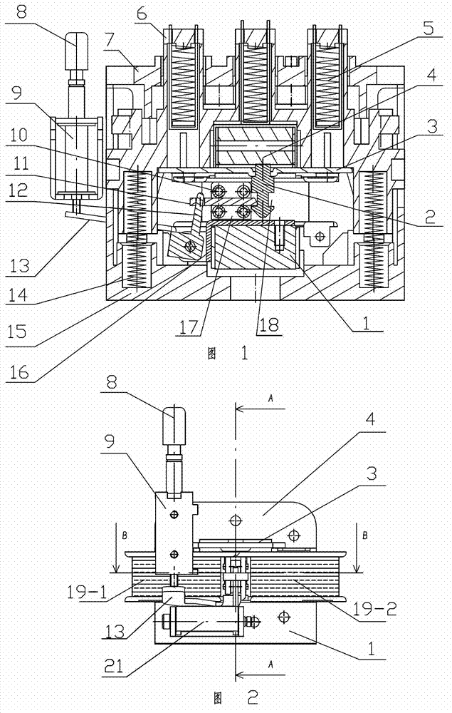
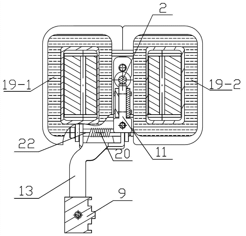
[0038] Such as figure 1 , figure 2 Shown: the present invention includes the dynamic and static contacts corresponding to each other, the movable contact is installed on the movable ferrule 6, the bottom of the movable ferrule 6 fixes the movable magnet 4 of the electromagnet through the hanging plate 3, and the static contact Fixed on the static contact fixing frame 7, the static contact fixing frame 7 is fixed on the contactor base 15, there is a static magnet 1 fixed on the contactor base 15 between the hanging plate 3 and the contactor base 15, and the static magnet 1 Two pull-in coils 19 are arranged on the top, and the center position of the static magnet 1 between the two pull-in coils 19-1, 19-2 is provided with a locking mechanism.

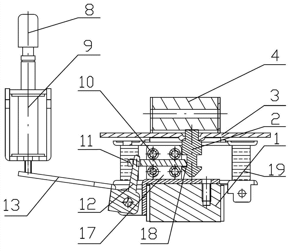
[0039] Such as figure 2 , image 3 and Figure 4 As shown: the locking mechanism includes a lock tongue 11 and a lock pin, the lock pin is fixed on the hanging plate 3, the lock tongue 11 is connected to the opening trip frame capab...

Embodiment 2

[0046] Such as Figure 5 , Figure 6 , Figure 7 As shown: the opening and tripping frame includes a tripping pin 12, a tripping arm 13 and a tripping shaft 23, and the tripping pin 12 and the tripping arm 13 are respectively fixedly connected to the tripping shaft 23, and the tripping shaft 23 is installed on the buckle seat 16, and the tripping torsion spring 20 is installed on the tripping rotating shaft 23, and the dead bolt 11 is connected on the tripping pin 12. The rest is the same as that of Embodiment 1, the action of the trip arm 13 is transmitted to the trip pin 12 through the trip shaft 23, so that the lock tongue 11 moves, and the same purpose is achieved, and the same beneficial effect is achieved.

[0047] It can be seen from the above embodiments that the present invention has a simple structure, realizes no-voltage operation, consumes no power and has no noise; the tripping force is reduced, and it is easy to realize tripping under pressure; the volume is sm...


PUM


Abstract

The invention relates to a straight-movement AC(Alternating Current) contactor with a lock catch arranged at the center, belonging to the technical field of low-voltage electric appliances. A moving contact is mounted on a moving mortice core, and a stationary contact is fixed on a stationary contact fixing stand which is fixed on a contactor base; a stationary magnet fixed on the contactor base is arranged between a hanger plate and the contactor base; and two attracting coils are arranged on the stationary magnet. The straight-movement AC contactor is characterized in that a lock catch mechanism is arranged at the central position of the stationary magnet between the two attracting coils; the lock catch mechanism comprises a spring bolt and a lock pin which is fixed on the hanger plate; the spring bolt is connected onto a brake separation tripping rack, and the brake separation tripping rack can restore automatically and is installed on a lock catch seat ; the lock catch seat is fixed on the stationary magnet; a brake separation tripper is correspondingly arranged at the outer end of a tripping force arm of the brake separation tripping rack; and the lower end of a stripping rod of the brake separation tripper contacts with the tripping force arm. The straight-movement AC contactor consumes no electric power and produces no noise during operation; the coils and the contacts can not easily be burned; and the straight-movement AC contactor is small in size, little in occupying room, and reasonable and compact in structure and is sensitive and reliable.

Description

technical field [0001] The invention relates to a central locking type direct running AC contactor, which belongs to the technical field of low-voltage electrical appliances. Background technique [0002] The AC contactor is the most widely used electrical device in electrical equipment. The direct-running AC contactor includes dynamic and static contacts corresponding to each other. The moving contacts are installed on the movable ferrule, and the static contacts are fixed on the static contact holder. On the top, the static contact fixing frame is fixed on the base of the contactor, and the bottom of the movable ferrule is equipped with a pull-in electromagnet and a moving magnet, which corresponds to the static magnet below and is installed on the base of the contactor. When working, power is supplied to the coil of the pull-in electromagnet, so that an attraction force is generated between the dynamic and static magnets of the electromagnet, and the movable ferrule is pu...

Claims


Application Information

Patent Timeline
Patent Type & Authority Applications(China)
IPC IPC(8): H01H50/32
Inventor 曲建胜董兆敏刘博李金莲王金凯范保珍
Owner 山东卓尔电气有限公司
Why Eureka
Try Eureka