Radiation detector and radiological image radiographing apparatus

A radiation detector and radiation image technology, which is applied to measurement devices, radiation control devices, instruments used for radiation diagnosis, etc., can solve the problems of decreased light emission, complicated manufacturing processes, damage to columnar parts, etc., and can suppress the deterioration of sensitivity. , the effect of improving quality and increasing sensitivity

Inactive Publication Date: 2013-03-06
FUJIFILM CORP
View PDF12 Cites 7 Cited by
  • Summary
  • Abstract
  • Description
  • Claims
  • Application Information

AI Technical Summary

Problems solved by technology

However, for increasing the film thickness of the scintillator layer, in addition to the problem of cost increase, there is also the following problem: the thicker the film thickness, the more it is necessary to increase the porosity in the initial part (root part) of the columnar crystal, As a result, the amount of light emitted at the initial portion decreases
Therefore, after the vapor deposition process, it is necessary to reduce the length of the abnormally grown columnar portion by pressing, etc., which complicates the manufacturing process.
In addition, the normal columnar part around the abnormal growth may be damaged due to extrusion

Method used


Image

  • Radiation detector and radiological image radiographing apparatus
  • Radiation detector and radiological image radiographing apparatus
  • Radiation detector and radiological image radiographing apparatus

Examples


no. 1 Embodiment approach

[0067] First, the configuration of the radiation detector 20 of the indirect conversion method according to the present embodiment will be described.

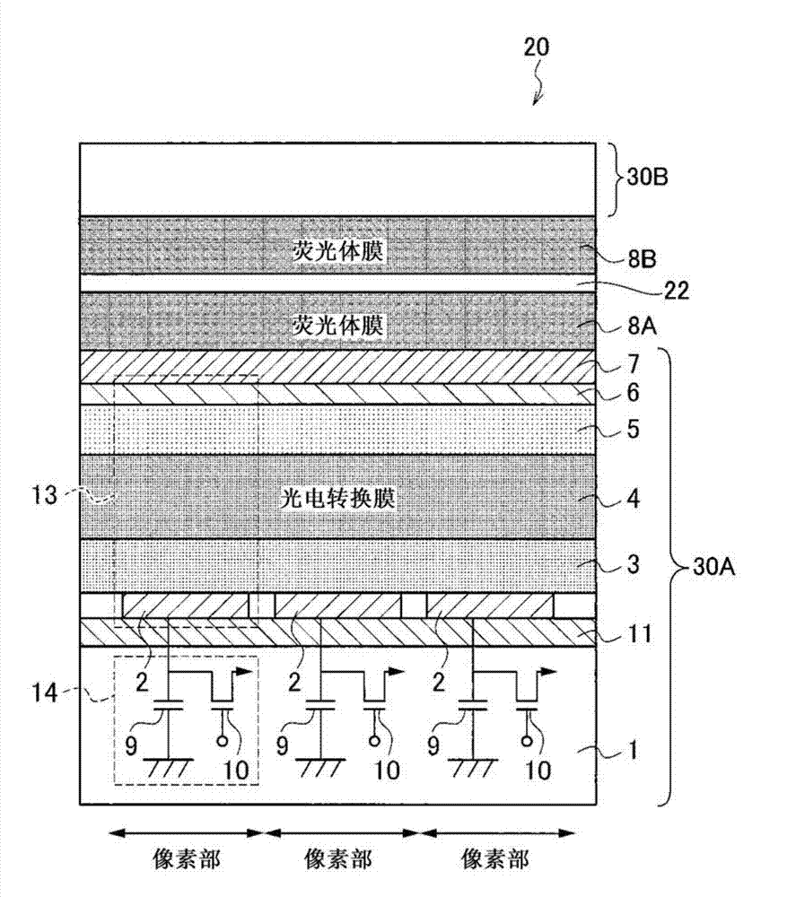
[0068] figure 1 It is a cross-sectional schematic diagram schematically showing the configuration of three pixel portions of the radiation detector 20 as one embodiment of the present invention.

[0069] In this radiation detector 20, a TFT substrate 30A, a scintillator 8A, a base layer 22, a scintillator 8B, and a TFT substrate 30B having the same configuration as the TFT substrate 30A are sequentially laminated from the side opposite to the radiation irradiation side, wherein the The TFT substrate 30A is formed by sequentially forming the signal output portion 14, the sensing portion 13, and the transparent insulating film 7 on the insulating substrate 1. Section 13 constitutes. As for the pixel unit, two or more pixel units are arranged on the substrate 1, and are configured such that the signal output unit 14 and the sen...

no. 2 Embodiment approach

[0172] Next, a second embodiment will be described.

[0173] First, refer to Figure 13 , the configuration of the radiation detector 20B of the indirect conversion method according to the second embodiment will be described. It should be noted that for Figure 13 Components that are the same as those in the first embodiment described above are denoted by the same symbols as those in the first embodiment described above, and descriptions thereof will be omitted.

[0174] like Figure 13 As shown, in the radiation detector 20B of this embodiment, a base layer 22A, a reflective layer 12, a scintillator 8A, an adhesive layer 23, a TFT substrate 30A, a base layer 22B, scintillator 8B and TFT substrate 30B.

[0175] Here, the reflective layer 12 is for reflecting visible light, and by forming the reflective layer 12 , light generated in the scintillators 8A and 8B can be efficiently guided to the TFT substrate 30A, thereby improving sensitivity. The method for forming the refl...

no. 3 Embodiment approach

[0181] Next, a third embodiment will be described.

[0182] First, refer to Figure 14 , the configuration of the radiation detector 20C of the indirect conversion method according to the third embodiment will be described. It should be noted that for Figure 14 Components that are the same as those in the above-mentioned second embodiment are assigned the same symbols as in the above-mentioned second embodiment, and description thereof will be omitted. It should be noted that, similar to the first embodiment, it is also preferable to control the front end of each columnar portion of the scintillator 8A in this embodiment so as to be as flat as possible.

[0183] like Figure 14 As shown, in the radiation detector 20C of this embodiment, a TFT substrate 30A, a scintillator 8A, an adhesive layer 23 , a TFT substrate 30B, a scintillator 8B, and a reflective layer 12 are sequentially laminated from the side opposite to the radiation X irradiated side. and base layer 22.

[0...


PUM


Abstract

There are provided a radiation detector and a radiological image radiographing apparatus capable of improving the quality of an obtained radiological image while suppressing the deterioration of the sensitivity of a phosphor layer according to the cumulative dose of radiation. In the radiation detector, a second scintillator which absorbs lower radiation energy than radiation energy absorbed by a first scintillator and whose deterioration of sensitivity according to the cumulative dose of radiation is larger than that of the first scintillator is provided at the downstream side of the first scintillator in the emission direction of the radiation. In addition, two substrates of a first substrate, which mainly acquires electric charges corresponding to light generated by the first scintillator, and a second substrate, which mainly acquires electric charges corresponding to light generated by the second scintillator, are provided.

Description

technical field [0001] The present invention relates to a radiation detector and a radiographic imaging device, and more particularly to a radiation detector for detecting irradiated radiation, and a radiographic imaging device for capturing a radiographic image displayed by the radiation detected by the radiation detector. Background technique [0002] In recent years, radiation detectors such as FPD (Flat Panel Detector (Flat Panel Detector)) have been put into practical use. In FPD, a radiation-sensitive layer is provided on a TFT (Thin Film Transistor (Thin Film Transistor)) active matrix substrate. Radiation such as X-rays can be directly converted into digital data. Compared with the conventional radiographic imaging apparatus using X-ray film or imaging plate, the radiographic imaging apparatus using this radiation detector has the ability to confirm the image in real time, and can also perform fluoroscopic imaging (moving image imaging) that continuously captures rad...

Claims


Application Information

Patent Timeline
Patent Type & Authority Applications(China)
IPC IPC(8): H01L27/146A61B6/00G01T1/20
CPCH01L27/146G01T1/2018H01L31/101H01L27/14661H01L27/14663A61B6/4216A61B6/4283G01T1/2006
Inventor 西纳直行中津川晴康大田恭义佐藤圭一郎
Owner FUJIFILM CORP
Why Eureka
Try Eureka