Swing arm descending control loop of hydraulic excavator

A technology of control loop and motor arm, applied in mechanically driven excavators/dredgers, etc., can solve problems such as cost increase, energy waste, complicated control valve structure, etc., and achieve the effect of improving stability and simple structure

Active Publication Date: 2015-05-20
SUNWARD INTELLIGENT EQUIP CO LTD
View PDF6 Cites 0 Cited by
  • Summary
  • Abstract
  • Description
  • Claims
  • Application Information

AI Technical Summary

Problems solved by technology

If the displacement of the hydraulic pump continues to increase at this time, it will not only cause waste of energy, but also cause adverse effects of system heating
However, this kind of regeneration channel makes the structure of the control valve complex because of the built-in check valve, which increases the cost
[0003] If the oil supply of the pump is completely cut off when the boom is lowered, and the flow adjustment is realized entirely by the gravity of the boom itself, the following problems will occur: First, when the boom is lowered too fast, the amount of regenerated oil is far behind the boom. The speed at which the boom is lowered will cause negative pressure in the rod chamber of the boom cylinder, which will cause air suction; second, when the bucket touches the ground, the boom will often be lowered to achieve the working conditions of supporting the car and leveling the ground. However, at this time, the conversion of potential energy and hydraulic energy is no longer performed to supply oil to the rod chamber of the boom cylinder, so that the boom cylinder cannot move

Method used


Image

  • Swing arm descending control loop of hydraulic excavator

Examples


Embodiment Construction

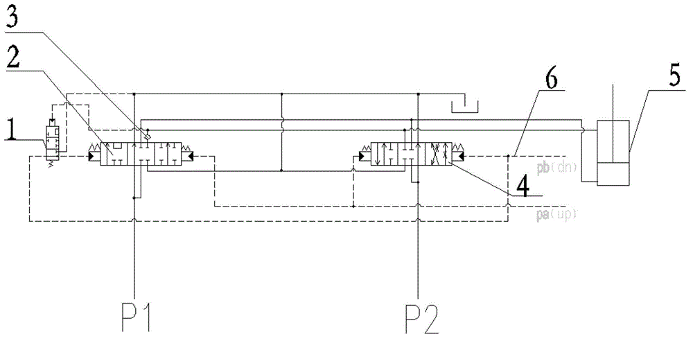
[0014] The present invention will be further described below in conjunction with the accompanying drawings and specific embodiments.

[0015] The first control valve 2 of the boom of this device is provided with a regeneration channel; the CT port of the second control valve 4 of the boom is provided with a throttle port, so that the oil return of the boom generates back pressure; There is a flow regeneration control valve 1 between the first control valve 2 of the boom, which automatically controls the on-off of the pilot signal of the first control valve 2 of the boom. The pilot signal of the flow regeneration control valve 1 is taken from the rod chamber of the boom cylinder 5, It can automatically realize the complete flow regeneration and regeneration cancellation according to the load change. During the lowering process of the boom, due to the action of the boom and the load gravity, part of the oil that originally flows back to the oil tank from the rodless chamber of t...


PUM


Abstract

The invention discloses a swing arm descending control loop of a hydraulic excavator. A swing arm first control valve is provided with a regeneration channel; a CT orifice of a swing arm second control valve is provided with a throttle orifice, so that swing arm oil return generates back pressure; a flow regeneration control valve is arranged between a swing arm descending pilot valve oil path and the swing arm first control valve and used for automatically controlling the on / off of a pilot signal of the swing arm first control valve; and the pilot signal of the flow regeneration control valve is derived from a swing arm rod cavity and can automatically realize complete regeneration and regeneration removal of flow quantity according to the change condition of load. In the swing arm descending process and under the action of the swing arm and the load gravity, one part of oil, which originally reflows to an oil tank, of a swing arm rodless cavity reflows to the oil tank through the throttle orifice and one part of the oil enters the rod cavity quickly through the regeneration channel of the swing arm first control valve, so that a pump is kept in low-discharge state, the power consumption is reduced, the oil temperature of the system is reduced, and the energy-saving effect is achieved. When a bucket is in contact with the ground or supports a vehicle, the pressure of the rod cavity is increased, the flow regeneration control valve is closed, the swing arm first control valve returns to the middle position, the regeneration channel is closed, and all the oil reflows to the oil tank through the CT throttle orifice of the swing arm second control valve, so the work efficiency is improved.

Description

technical field [0001] The invention relates to the technical field of engineering machinery, in particular to a hydraulic excavator boom lowering control circuit. Background technique [0002] At present, the main control valve of the boom lowering control loop is mainly composed of the first boom control valve 2 and the second boom control valve 4, and the loop includes a boom raising loop, a boom lowering loop, and a boom regeneration loop. Generally, the return oil of the hydraulic cylinder in the hydraulic excavator must be returned to the oil tank. If only part of the return oil of the hydraulic cylinder returns to the oil tank, the rest of the flow will merge with the pressure oil output by the pump and flow into the oil inlet chamber of the hydraulic cylinder. This circuit is called a regenerative circuit. A common boom regeneration method is to set a compensation channel in a boom control valve, and set a one-way valve in the compensation channel. In the working p...

Claims


Application Information

Patent Timeline
Patent Type & Authority Patents(China)
IPC IPC(8): E02F3/43
Inventor 何清华郭勇张新海高珊陈桂芳
Owner SUNWARD INTELLIGENT EQUIP CO LTD
Why Eureka
Try Eureka