Swinging arm mechanism controlled by using double cams

A rocker arm mechanism, double cam technology, applied in mechanical equipment, engine components, machines/engines, etc., can solve the problem that there is no way to change the valve lift and cycle of the engine, affect engine power, economy and emissions, complex structure, etc. problems, to achieve the effect of improving fuel economy, improving charging efficiency, and reducing exhaust pollution

Inactive Publication Date: 2013-03-13
TIANJIN UNIV
View PDF6 Cites 4 Cited by
  • Summary
  • Abstract
  • Description
  • Claims
  • Application Information

AI Technical Summary

Problems solved by technology

When the engine operating conditions change and the valve lift and cycle need to be reduced, for the traditional cam drive mechanism shown in Figure 1, there is no way to change the valve lift and cycle of the engine, so it affects the engine power, economy and emissions
[0004] With the advancement of technology, the variable cam lift mechanism of BMW and the variable cam lift mechanism introduced by Toyota have appeared, but these structures are relatively complicated and costly.

Method used


Image

  • Swinging arm mechanism controlled by using double cams
  • Swinging arm mechanism controlled by using double cams

Examples


Embodiment Construction

[0021] The double-cam controlled rocker mechanism of the present invention will be described in detail below with reference to the embodiments and the accompanying drawings.

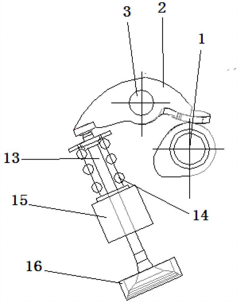
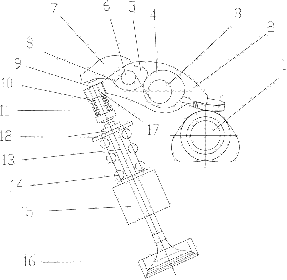
[0022] Such as figure 2 As shown, the rocker arm mechanism controlled by double cams of the present invention includes: a camshaft 1, a main rocker arm 2 rotatably connected to the main rocker arm shaft 3, one end of the main rocker arm 2 is connected to the The camshaft 1 is connected in close contact, and the main rocker arm 2 swings around the main rocker arm shaft 3 as the axis rotates with the rotation of the camshaft 1, and the other end of the main rocker arm 2 is integrally provided with a pressure ring 17, so The top of the valve stem 13 of the internal combustion engine is provided with a tappet mechanism for compressing the valve stem 13, the pressure ring 17 is slidably connected with the tappet mechanism, and the main rocker arm 2 is provided with the pressure ring 17. This end is also fixe...


PUM


Abstract

The invention discloses a swinging arm mechanism controlled by using double cams. The swinging arm mechanism comprises a main swinging arm which is rotationally connected to a main swinging arm shaft, wherein one end of the main swinging arm is tightly contacted with a camshaft; a pressure ring is arranged at the other end of the main swinging arm; a tappet mechanism is arranged at the top end of a valve rod of an internal combustion engine; the pressure ring is connected with the tappet mechanism in a sliding way; a secondary swinging arm shaft is fixedly arranged at one end of the main swinging arm where the pressure ring is arranged; a secondary swinging arm is rotationally hinged on the secondary swinging arm shaft; a second cam is formed on the end part of one end of the secondary swinging arm which is positioned on the secondary swinging arm shaft; a control cam is fixedly arranged on the main swinging arm shaft; the cam is tightly contacted and connected with the second cam through a tension spring; a convex part is formed at one end of the second swinging arm which is far away from the second cam; and the convex part is contacted tightly or in interval contact with the tappet mechanism which is arranged at the top end of the valve rod of the internal combustion and is used for compressing the valve rod. Due to the adoption of the swinging arm mechanism, the lift of a transmission mechanism can be adjusted easily in the running processes of a mechanical system and the internal combustion engine, and the performance of the mechanical system and the internal combustion engine can be improved.

Description

technical field [0001] The invention relates to a cam rocker mechanism. In particular, it relates to a rocker arm mechanism controlled by double cams with variable cam lift. Background technique [0002] Mechanical systems including internal combustion engines often need to change the lift of the camshaft to achieve the purpose of improving performance. For example, due to structural limitations of traditional internal combustion engines, the lift of the camshaft cannot be adjusted, thus limiting the improvement of its performance. [0003] As shown in Figure 1, in the traditional internal combustion engine cam valve transmission structure, there is only one rocker arm 2, and the rotation of the camshaft 1 directly drives the rocker arm 2 to swing, and then drives the valve stem 13 for linear motion. When the engine operating conditions change and the valve lift and cycle need to be reduced, for the traditional cam drive mechanism shown in Figure 1, there is no way to chan...

Claims


Application Information

Patent Timeline
Patent Type & Authority Applications(China)
IPC IPC(8): F01L1/18F01L1/22
Inventor 林建生
Owner TIANJIN UNIV
Why Eureka
Try Eureka