U-shaped ball valve for slurry mixing and ash discharging

A U-shaped, slurry mixing technology, applied to valve devices, cocks including cut-off devices, engine components, etc., can solve problems such as valve damage and failure, particle inclusion, long-term erosion, etc., to achieve low operating failure rate, improve service life, The effect of reducing manufacturing costs

Inactive Publication Date: 2013-03-13
DAZHONG VALVE FACTORY ZHEJIANG PROV
View PDF6 Cites 5 Cited by
  • Summary
  • Abstract
  • Description
  • Claims
  • Application Information

AI Technical Summary

Problems solved by technology

[0002] Power plant coal slurry conveying system, alumina industrial ore slurry pipeline, slurry mixing and ash unloading valves used in steel plant furnace ash unloading, ash unloading and dust removal valves used in blast furnace flue, there are single valves available for selection Seat fixed ball valve (dust unloading ball valve), eccentric hemispherical valve, Y-shaped slurry valve, etc.; because the medium contains a large amount of granular hard solids, during the opening and closing process of the valve, particles are often mixed between the valve sealing pairs. In the slightest, the seal is not tight, and in severe cases, it will cause valve damage and failure
Solid granular medium will deposit and agglomerate in the inner cavity of the valve, often causing the sticking and jamming of the opening and closing parts and the valve cavity
In addition, these high-hardness solid media such as coal powder and ash will scour the sealing surface of the valve and the surface of the closing part for a long time at a high flow rate; the smoke and harmful gases in the flue system will also form on the sealing surface of the valve and the surface of the closing part. Coking, fouling, etc., all have adverse effects on the sealing and life of the valve

Method used


Image

  • U-shaped ball valve for slurry mixing and ash discharging
  • U-shaped ball valve for slurry mixing and ash discharging
  • U-shaped ball valve for slurry mixing and ash discharging

Examples


Embodiment Construction

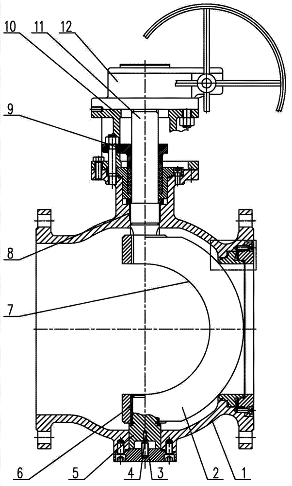
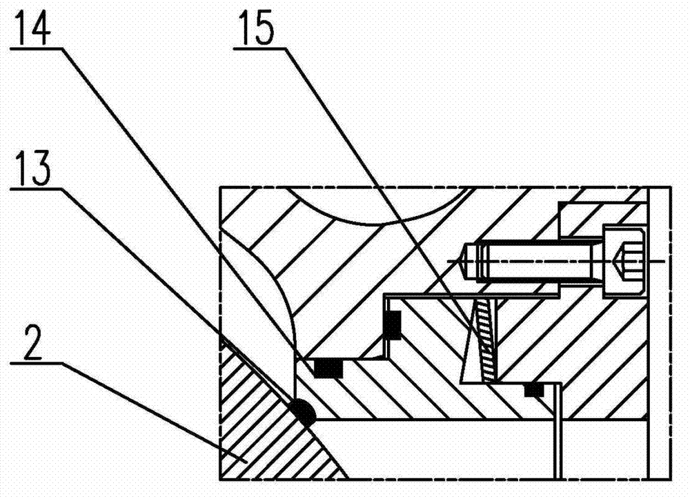
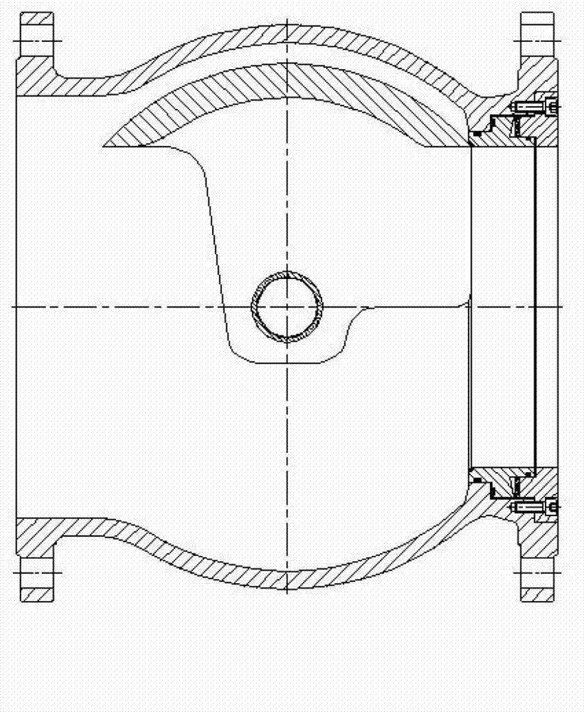
[0011] A U-shaped ball valve for slurry mixing and ash unloading, such as figure 1 As shown, it includes a valve body 1, a sphere 2, and a lower end cover 3. The lower end of the valve body 1 is provided with a lower end cover 3, and the lower end cover 3 is connected with the lower fixed shaft 5 through the adjusting screw 4; the lower fixed shaft 5 passes through the lower shaft sleeve 6 is movably connected with the rotating shaft at the bottom of the ball 2; the rotating shaft at the top of the ball 2 is connected with the bottom end of the valve stem 11 through the upper bushing 8; 12 is set on the bracket 10, and the bottom of the bracket 10 is connected to the top of the valve body 1 through the packing system structure 9; in the actual implementation process of the patent, the valve can complete stable and reliable opening and closing actions driven by the actuator 12, realizing Pipeline connection and disconnection. The valve is completely designed for working condit...


PUM


Abstract

The invention discloses a U-shaped ball valve for slurry mixing and ash discharging. The U-shaped ball valve comprises a valve body, a ball body and a lower end cover, wherein the lower end of the valve body is provided with the lower end cover; the lower end cover is connected with a lower stationary shaft through a set screw; the lower stationary shaft is movably connected with a rotating shaft at the bottom of the ball body through a lower shaft sleeve; the rotating shaft at the top of the ball body is connected with the bottom end of a valve rod through an upper shaft sleeve; and the valve rod penetrates through a filler system structure and the rear top end of a bracket to be connected with an executing mechanism. The U-shaped ball valve has the beneficial effect that the design of a non-eccentric wear-resistant ball body with a U-shaped flow passage port, a streamline-shaped outlet and valve cavity ball hiding is adopted by the designed and developed U-shaped ball valve for slurry mixing and ash discharging. A valve seat with a scraper port is designed to be provided with a labyrinth type disc spring pre-tightening mechanism. The U-shaped ball valve has the advantages of capability of effectively solving the problems, low operation failure rate, capability of greatly prolonging the service life of the valve, compact structure, light weight, capabilities of reducing the manufacturing cost and realizing mounting at any position, quick opening and closing and remote control and the like.

Description

technical field [0001] The invention relates to a ball valve, in particular to a U-shaped ball valve for slurry mixing and ash unloading. Background technique [0002] Power plant coal slurry conveying system, alumina industrial ore slurry pipeline, slurry mixing and ash unloading valves used in steel plant furnace ash unloading, ash unloading and dust removal valves used in blast furnace flue, there are single valves available for selection Seat fixed ball valve (dust unloading ball valve), eccentric hemispherical valve, Y-shaped slurry valve, etc.; because the medium contains a large amount of granular hard solids, during the opening and closing process of the valve, particles are often mixed between the valve sealing pairs. If it is light, the seal is not tight, and if it is serious, it will cause damage to the valve and fail. Solid granular medium will deposit and agglomerate in the inner cavity of the valve, often causing the opening and closing parts to stick to the v...

Claims


Application Information

Patent Timeline
Patent Type & Authority Applications(China)
IPC IPC(8): F16K5/06F16K5/08F16K5/20
Inventor 金志渊
Owner DAZHONG VALVE FACTORY ZHEJIANG PROV
Why Eureka
Try Eureka