Preparation method of cellular V-Ti low-temperature smoke denitration catalyst

A denitrification catalyst and low-temperature flue gas technology, applied in chemical instruments and methods, physical/chemical process catalysts, separation methods, etc., can solve problems such as unfavorable long-term operation of the denitrification system, difficulty in ensuring catalyst life, and large bed resistance, etc., to achieve Guaranteed service life, good mechanical properties and low smoke resistance

Active Publication Date: 2013-03-20
CECEP L&T ENVIRONMENTAL TECH
View PDF7 Cites 47 Cited by
  • Summary
  • Abstract
  • Description
  • Claims
  • Application Information

AI Technical Summary

Problems solved by technology

The bed resistance of granular catalysts in engineering applications is relatively large, which is not conducive to the long-term operation of the denitrification system; 2 Oxidation to SO 3 , leading to catalyst deactivation, it is difficult to guarantee the life of the catalyst. At present, there is no industrialized low-temperature honeycomb denitrification catalyst in China.

Method used


Image

  • Preparation method of cellular V-Ti low-temperature smoke denitration catalyst
  • Preparation method of cellular V-Ti low-temperature smoke denitration catalyst

Examples

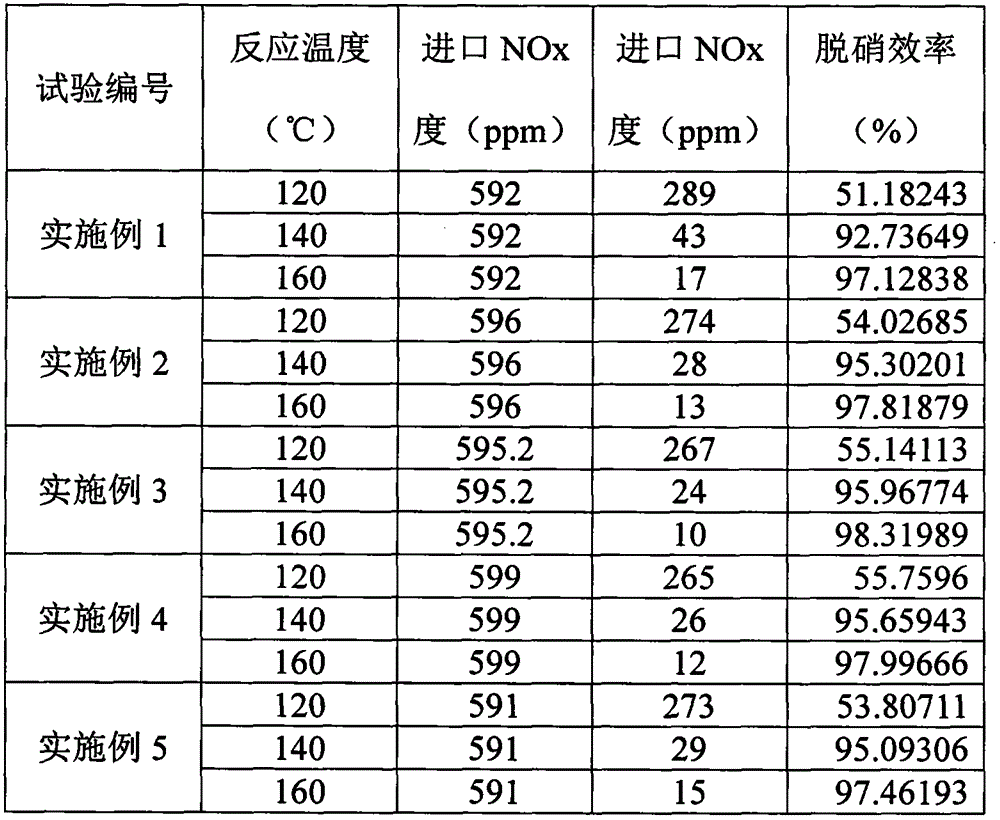

Embodiment 1

[0029] (1) Mixing process

[0030] In the reactor, add a certain amount of deionized water and heat to 80 ° C, TiO 2 , providing V 2 o 5 The salt, salt and oxalic acid that provide oxide additives are added to the reactor according to the mass of 280kg: 17kg: 20kg: 40kg, and react for 1h. After the material in the reactor is muddy, dry at 160°C for 50-60min, transfer to the calciner Calcined in the kiln at 250-450°C for 50-60min and pulverized into granular catalyst.

[0031] (2) Forming process

[0032] Take by weighing the granular catalyst 200kg that mixing process gained, add stearic acid 8kg, add carboxymethacrylic acid 6.4kg, add glass fiber 11kg, add pure ammoniacal liquor 6kg, add deionized water 80kg through mud refining, vacuum mud refining, in Aged for 24 hours under constant temperature and humidity conditions, molded, dried at 60°C for 60-90 hours, and sintered in a tunnel kiln at 180-450°C for 2 hours to become a honeycomb denitrification catalyst.

Embodiment 2

[0034] (1) Mixing process

[0035] In the reactor, add a certain amount of deionized water and heat to 80 ° C, TiO 2 , providing V 2 o 5 The salt, the salt and oxalic acid that provide the oxide auxiliary agent are added in the reactor according to the mass of 280kg: 30.2kg: 20kg: 40kg, and react for 1h. Calcined at 250-450°C for 50-60 minutes in a calcining kiln and pulverized into a granular catalyst.

[0036] (2) forming process (same as the forming process of embodiment 1)

Embodiment 3

[0038] (1) Mixing process

[0039] In the reactor, add a certain amount of deionized water and heat to 80 ° C, TiO 2 , providing V 2 o 5 The salt, salt and oxalic acid that provide oxide additives are added to the reactor according to the mass of 280kg: 26kg: 20kg: 40kg, and react for 1h. The material in the reactor is in the form of mud, dried at 160°C for 50-60min, and transferred to the calciner. Calcined in the kiln at 250-450°C for 50-60min and pulverized into granular catalyst.

[0040] (2) forming process (same as the forming process of embodiment 1)


PUM

PropertyMeasurementUnit
thicknessaaaaaaaaaa

Abstract

The invention discloses a preparation method of a cellular V-Ti low-temperature smoke denitration catalyst. The catalyst takes nano-grade TiO2 as a carrier and occupies 70-90% of the mass of the catalyst; an active component is V2O5 and occupies 5-15% of the mass of the catalyst; and a metal oxide auxiliary is one or more of oxides of Cr, Mn, Cu, Ce, W and Mo and occupies 4-16% of the mass of the catalyst. A preparation process of the catalyst is formed by a material mixing process and a molding process; the material mixing process comprises a secondary material mixing step and a calcining step; the NOx removing rate is more than 95% by using the activity of the catalyst at a temperature of 140-260 DEG C; the suitable service life and the mechanical service life of the catalyst are greatly prolonged; and the preparation method is applicable to industrial production and the application of a low-temperature smoke SCR (Selective Catalytic Reduction) denitration system.

Description

technical field [0001] The invention belongs to the technical field of catalysts, and mainly relates to a preparation method of a honeycomb V-Ti low-temperature flue gas denitrification catalyst. Background technique [0002] Since Japan developed a commercial denitration catalyst in the 1970s, SCR denitration technology has made engineering progress and has become the mainstream technology for flue gas denitration in thermal power plants. Since V 2 o 5 / TiO 2 The catalytic activity temperature range of the system is between 280-450°C, and the SCR is often arranged between the boiler economizer and the air preheater. However, the flue gas of this arrangement contains a large amount of SO 2 、K 2 O, CaO and As 2 o 3 etc., will cause catalyst poisoning, and high concentration of fly ash will cause blockage and wear of the catalyst, reducing its service life. [0003] Due to the limitations of space and pipelines, it is very difficult and expensive to retrofit existing b...

Claims


Application Information

Patent Timeline
Patent Type & Authority Applications(China)
IPC IPC(8): B01J23/22B01J23/34B01J23/30B01J23/28B01J23/847B01D53/86B01D53/56
Inventor 宋宝华王昕竑王中原林德海杨鹤峰
Owner CECEP L&T ENVIRONMENTAL TECH
Why Eureka
Try Eureka