
Multi-functional wet axle of 5-10 T fork-lift truck

A multi-functional, wet technology, applied in the directions of axles, wheels, vehicle parts, etc., can solve the problems of easy slippage between friction plates and spacers, slow braking response time, low safety, etc., to shorten the braking response time, The effect of stable and reliable braking and simplified assembly process

Inactive Publication Date: 2013-03-20
ANHUI HELI CO LTD
View PDF6 Cites 7 Cited by
  • Summary
  • Abstract
  • Description
  • Claims
  • Application Information

AI Technical Summary

Problems solved by technology

[0002] At present, the brakes of domestic 5-10T forklift drive axles all adopt dry brakes. The brake system is exposed to the external working environment and is easily affected by water erosion, dust, oil, etc. The brakes are relatively affected by the outside world and are safe. low safety, especially in some coastal ports and wharves, it is prone to danger
The wet bridges for forklifts under development have the following problems: 1. The cooling system used by the wet brakes shares the oil source with the hydraulic working device, resulting in a large volume of the hydraulic oil tank to ensure the heat dissipation area, and the need to increase the cooling fan, resulting in a complex car body structure; at the same time After the fan is installed, the power supply of the engine is likely to be insufficient due to the power limitation of the engine. When using it, a high-power engine must be selected on the basis of the original one.
The manufacturing cost of the whole machine is higher; 2. The oil film between the friction plate and the spacer is not squeezed cleanly during braking, and the friction plate and the spacer are easy to slip each other during braking, resulting in slow braking response time, and wet brakes are prone to sudden high temperature sintering

Method used


Image

  • Multi-functional wet axle of 5-10 T fork-lift truck
  • Multi-functional wet axle of 5-10 T fork-lift truck
  • Multi-functional wet axle of 5-10 T fork-lift truck

Examples


Embodiment

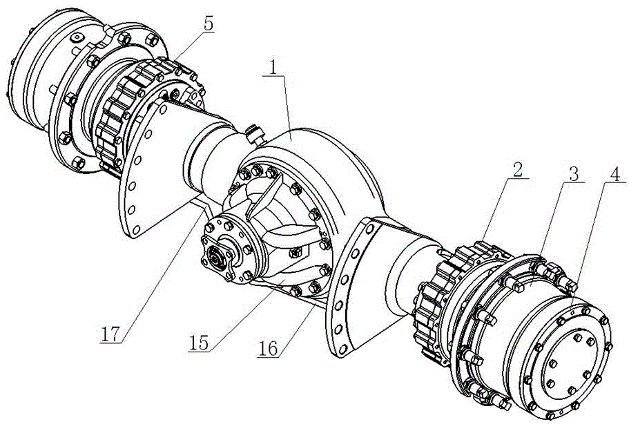
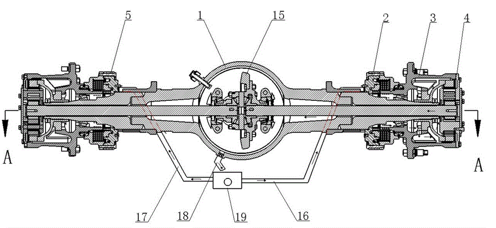
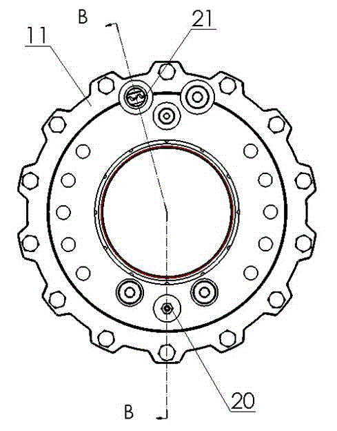
[0026] see figure 1 , figure 2 , Figure 5 , the multi-functional wet axle of a 5-10 ton forklift includes a drive axle housing 1 and a final reducer assembly 15, the left and right sides of the drive axle housing are respectively installed with a right brake 2 and a left brake 5 in sequence, and the outer side of the right brake 2 and the A wheel hub assembly 3 and a wheel-side planetary reduction mechanism 4 are respectively installed on the drive axle housing 1 outside the left brake 5; both the right brake 2 and the left brake 5 are wet brakes. The first lubricating oil passage 21 is opened on the end surface of the inner housing 11 of the brake corresponding to the final reducer assembly 15, and the first lubricating oil passage 21 of the brakes on both sides is respectively connected with one end of the right cooling oil pipe 16 and the left cooling oil pipe. 17, the other end of the right cooling oil pipe 16 is connected to the first port of the tee pipe 19, and the ...


PUM


Abstract

The invention relates to a multi-functional wet axle of a 5-10 T fork-lift truck. Service brakes of the drive axle are wet brakes; inner shells of the left brake and the right brake are provided with a first lubricating oil passage respectively; the first lubricating oil passages on the two sides are communicated with one ends of a right cooling oil pipe and a left cooling oil pipe respectively; the other ends of the right cooling oil pipe and the left cooling oil pipe are connected with a first port and a second port of a three-way pipe respectively; a cooling oil outlet pipe is arranged at the bottom of a drive axle shell corresponding to a main speed reducer assembly; a wheel hub body is provided with an oil drainage hole, a second lubricating oil passage and a third lubricating oil passage respectively; a third port of the three-way pipe and the cooling oil outlet pipe are communicated with an outlet and an inlet of a lubricating pump respectively; and thus, a forced circulatory lubrication system is formed. The service life of the wet axle is 3-5 times the service life of normal drum brakes, and the brake performance does not decline after the wet axle is used for more than three years; and the problem of insufficient engine power supply caused by large size of a hydraulic oil tank and additional arrangement of a cooling fan due to sharing of a cooling mechanism with a hoisting system is solved.

Description

technical field [0001] The invention belongs to the technical field of forklift truck axles, and in particular relates to a wet bridge for 5-10 ton forklift trucks. Background technique [0002] At present, the brakes of domestic 5-10T forklift drive axles all adopt dry brakes. The brake system is exposed to the external working environment and is easily affected by water erosion, dust, oil, etc. The brakes are relatively affected by the outside world and are safe. The safety is low, especially in some coastal ports and wharves, it is prone to danger. The wet bridges for forklifts under development have the following problems: 1. The cooling system used by the wet brakes shares the oil source with the hydraulic working device, so the hydraulic oil tank has a large volume to ensure the heat dissipation area, and cooling fans must be added, resulting in a complex car body structure; at the same time After the fan is installed, the power supply of the engine is likely to be in...

Claims


Application Information

Patent Timeline
Patent Type & Authority Applications(China)
IPC IPC(8): B60B35/00
Inventor 马乙周齐齐张丽郑海香陈先成刘宗其袁正
Owner ANHUI HELI CO LTD
Learn More