
Aircraft fluidic thrust vector control system

A technology of jet thrust and vector control, which is applied in the field of aerospace, can solve unseen problems, achieve the effects of improving positioning accuracy, reducing response time, and reducing weight

Inactive Publication Date: 2013-03-27
BEIJING INSTITUTE OF TECHNOLOGYGY
View PDF4 Cites 26 Cited by
  • Summary
  • Abstract
  • Description
  • Claims
  • Application Information

AI Technical Summary

Problems solved by technology

At present, the application of the Coanda effect to the jet thrust vector to realize the 360° attitude control system of the aircraft has not yet seen related applications

Method used


Image

  • Aircraft fluidic thrust vector control system
  • Aircraft fluidic thrust vector control system
  • Aircraft fluidic thrust vector control system

Examples


Embodiment Construction

[0026] The present invention will be described in detail below with reference to the accompanying drawings and examples.

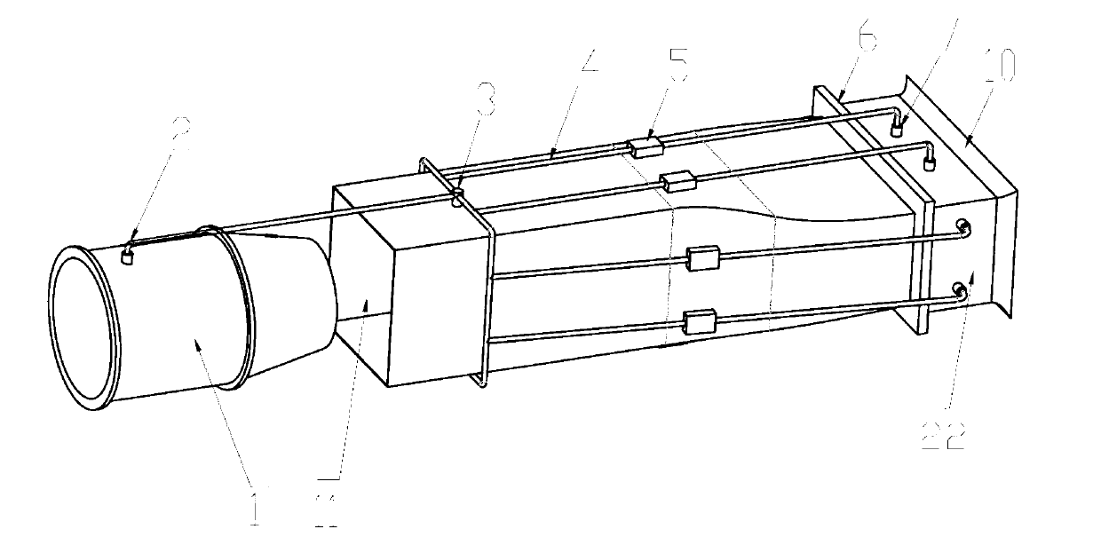
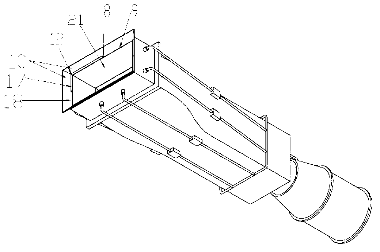
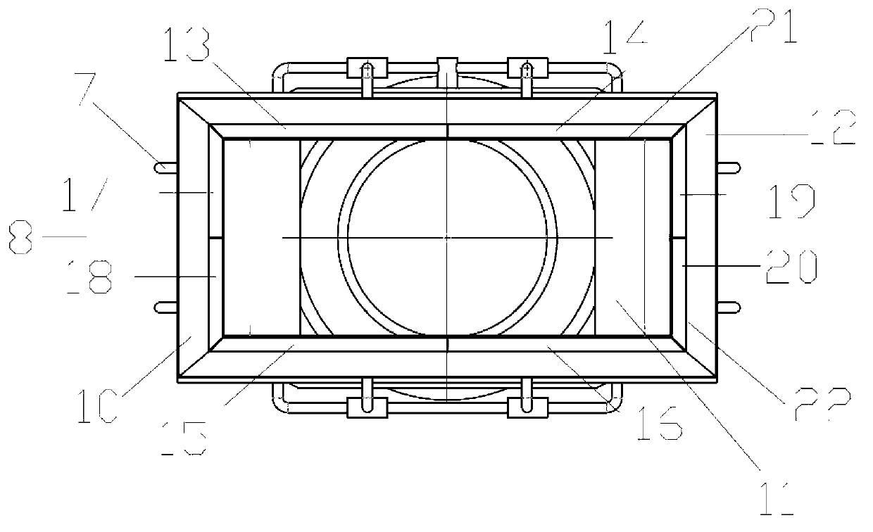
[0027] The present invention provides an aircraft jet thrust vector control system, comprising a gas turbine engine 1, a main airflow passage 11, a secondary flow nozzle 4, a secondary flow passage assembly and a Coanda effect surface 10, such as figure 1 shown.

[0028] Wherein, the main air flow channel 11 is arranged at the tail of the shrinking nozzle of the engine 1, coaxial with the engine 1, and for the convenience of processing, the main air flow channel 11 can be set as a cuboid. The contracting nozzle of the engine 1 discharges high-pressure gas as the axial main airflow of the control system, and the main airflow flows along the axial main airflow channel 11 to the tail of the jet thrust vector control system to generate axial propulsion and push the aircraft forward. Utilize the directionality of the high-pressure jet stream of the turbocharge...


PUM


Abstract

The invention discloses an aircraft fluidic thrust vector control system. With the control system, 306-degree flying attitudes of the aircraft can be controlled; response time of the control system is shortened; control precision of the control system is increased; a structure of the control system is simplified; and the weight of the aircraft is reduced. The aircraft fluidic thrust vector control system comprises a fuel gas turbine engine, a main airflow channel, a secondary flow nozzle, a secondary flow channel assembly and a Coanda effect surface. A small part of the gas is introduced out from an engine compression chamber to be used as a secondary flow gas source of the vector thrust control system in the same direction, and is injected into the secondary flow channel by using a Coanda effect. A wall attachment effect is produced after the secondary flow in the same direction with the main airflow flows through the Coanda effect surface, and Coanda effect is further generated by guiding the main airflow along the wall attachment direction, so that a deflection torque is obtained. Precision control for pitching, being off-course and rolling of the aircraft can be realized by controlling the outflow direction and the flow rate of the secondary flow.

Description

technical field [0001] The invention relates to an aircraft jet thrust vector control system, which belongs to the technical field of aerospace. Background technique [0002] In the traditional aircraft control system design, people use the asymmetric aerodynamic moment generated by the deflection of the rudder surface as the steering moment to control the flight attitude of the aircraft such as turning, climbing, diving, and rolling. This control mode must be supplemented by many complicated and heavy hydraulic or electro-hydraulic drive steering gear and other supporting related equipment, and the installation of the rudder surface destroys the continuous smooth wing, and there are many gaps, resulting in a large leakage At the same time, the deflection of the rudder surface will also increase the radar cross section (RCS) value of the aircraft, which is not conducive to stealth. Later, people installed gas rudder surfaces behind the tail engine of the aircraft to generat...

Claims


Application Information

Patent Timeline
Patent Type & Authority Applications(China)
IPC IPC(8): B64C15/02
Inventor 柴森春李俊董立静张百海夏元清
Owner BEIJING INSTITUTE OF TECHNOLOGYGY
Learn More