Optical fiber sensor for detecting natural gas pipeline leakage

A fiber optic sensor and natural gas pipeline technology, applied in pipeline systems, gas/liquid distribution and storage, mechanical equipment, etc., can solve problems such as poor positioning effect, poor anti-interference ability, and inability to effectively solve the problem of gas pipeline leakage detection. Achieve adjustable detection sensitivity, high sensitivity, and good noise isolation

Inactive Publication Date: 2013-03-27
BC P INC CHINA NAT PETROLEUM CORP +1
View PDF9 Cites 8 Cited by
  • Summary
  • Abstract
  • Description
  • Claims
  • Application Information

AI Technical Summary

Problems solved by technology

However, this type of technology is affected by interference events around the pipeline when monitoring leakage, has a high system false alarm rate, and has poor anti-interference ability
[0011] Throughout the various pipeline leakage monitoring technologies at home and abroad, the current commonly used negative pressure wave method, flow balance method, pressure slope and other oil pipeline leakage detection technologies cannot effectively solve the problem of gas pipeline leakage detection, especially for Identification and location of tiny leaks
Based on the good sensing characteristics of optical fibers, optical fiber sensing technology has been developed rapidly. Among them, an optical cable laid in the same ditch as a pipeline is used as a gas leakage sensor. Although the sensitivity is higher than that of traditional technologies, its positioning effect is poor. , can not fully meet the application requirements of natural gas pipeline leakage monitoring

Method used


Image

  • Optical fiber sensor for detecting natural gas pipeline leakage
  • Optical fiber sensor for detecting natural gas pipeline leakage
  • Optical fiber sensor for detecting natural gas pipeline leakage

Examples


Embodiment Construction

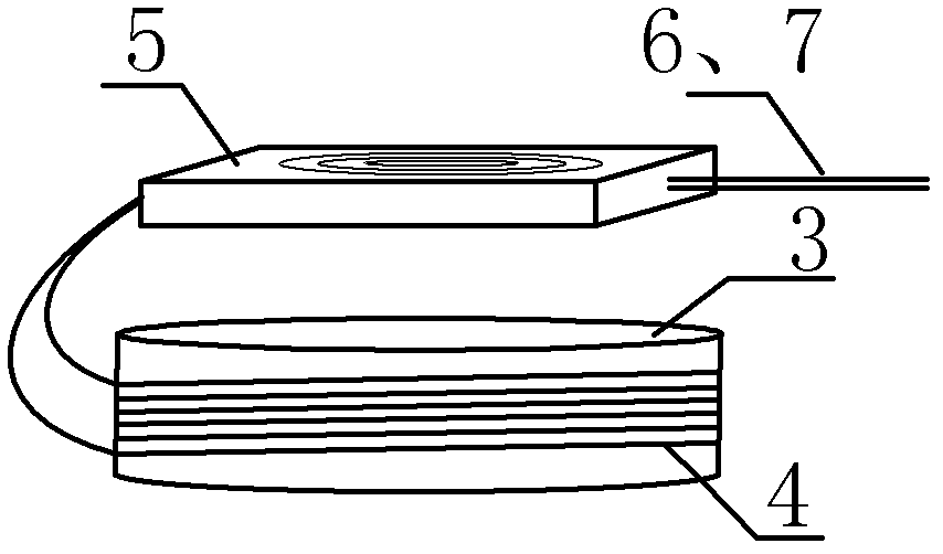
[0028] Embodiment. The composition of this example is as image 3 As shown, an optical fiber sensor 1 is installed every 1.5 km on the pipeline body, and an optical fiber sensor 1 senses a leakage signal at an axial point on the natural gas pipeline. By evenly distributing a plurality of optical fiber sensors 1 on the pipeline, the leakage of the entire pipeline can be detected. This optical fiber sensor is made up of elastic cylinder 3, optical fiber interferometer 4 and pigtail fiber box 5 (see image 3 ); wherein, the interference arm of the optical fiber interferometer is uniformly and orderly wound on the periphery of the elastic cylinder, and the optical fiber and the cylinder are tightly bonded together with an adhesive, and the remaining optical fiber interferometer and its related devices after winding will be Neatly coiled in the pigtail fiber box 5, the input and output optical fibers 6, 7 are exposed; the pigtail box 5 is fixed on the top of the elastic cylinder 3...


PUM


Abstract

The invention relates to an optical fiber sensor which is suitable for a natural gas pipeline leakage detection system. The optical fiber sensor consists of an elastic cylinder (3), a fiber optic interferometer (4) and a tail fiber disk fiber box (5), wherein interference arms of the fiber optic interferometer are uniformly and orderly wound on the periphery of the elastic cylinder (3); an optical fiber and the elastic cylinder are tightly bonded together by using a bonding agent; the fiber optic interferometer left after winding and relevant devices of the fiber optic interferometer are orderly wound in the tail fiber disk fiber box (5); the tail fiber disk fiber box (1) is fixed on the top of the elastic cylinder (3) by using a bonding agent; the elastic cylinder (3) is a steel short cylinder of which the bottom is inwardly depressed and the radian is consistent with that of the outer surface of a pipeline; and during installation of the sensor, the inwardly-depressed end of the elastic cylinder (3) is bonded on the surface of a natural gas pipeline by using a bonding agent. A front end probe with high positioning accuracy and high sensitivity is provided for a quasi-distributed natural gas pipeline leakage detection system.

Description

technical field [0001] The invention relates to an optical fiber sensor suitable for a natural gas pipeline leakage detection system, and relates to the technical fields of mechanical vibration measurement, impact measurement and pipeline system. Background technique [0002] At present, the total length of pipelines built in the world has reached 2.5 million kilometers, which has surpassed the total mileage of railways and has become the main mode of energy transportation in the world. Oil transportation in developed countries and oil-producing regions in the Middle East has all realized pipelines. my country's pipelines have also developed rapidly in recent years, with a total length of more than 70,000 kilometers. A large energy pipeline network has initially formed across the east, west, north and south, covering the whole country, and connecting overseas. Pipeline transportation has become the deployment of strategic energy such as oil and gas. The main method of deliver...

Claims


Application Information

Patent Timeline
Patent Type & Authority Applications(China)
IPC IPC(8): F17D5/02
Inventor 张金权丁树义杨文明李维李刚索娜徐贺许伟瑞王丽吴志平
Owner BC P INC CHINA NAT PETROLEUM CORP
Why Eureka
Try Eureka