Automatic cutting separator for waste CRT (cathode ray tube) display

A CRT display and automatic cutting technology, applied in glass cutting devices, glass manufacturing equipment, manufacturing tools, etc., can solve the problems of low efficiency, long operation time, high cost of wastewater treatment, etc., and achieve simple and flexible operation, low labor intensity, and easy treatment fast effect

Active Publication Date: 2013-04-03
YANGZHOU NINGDA NOBLE METAL CO LTD
View PDF4 Cites 7 Cited by
  • Summary
  • Abstract
  • Description
  • Claims
  • Application Information

AI Technical Summary

Problems solved by technology

The fusion method utilizes the characteristics that the softening temperature of the frit glass is lower than that of the cone glass and screen glass, and heats the entire glass envelope to the softening temperature of the frit glass, while the cone glass and screen glass have not softened yet, and the tube is kept at a certain inclination Angle, can realize the natural separation of the cone screen, the operation time of this method is long, generally need 6 ~ 8h
[0010] (6) Use nitric acid, hydrofluoric acid, etc. to dissolve the joints of screens and cones to separate them. The cost of subsequent wastewater treatment is high and the efficiency is low.

Method used


Image

  • Automatic cutting separator for waste CRT (cathode ray tube) display

Examples


Embodiment Construction

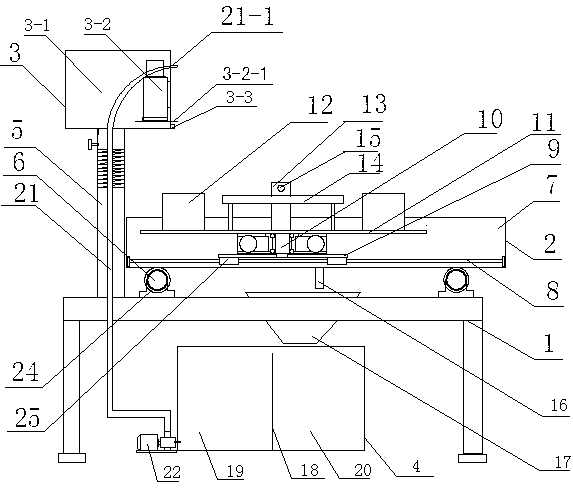
[0022] Such as figure 1 As shown, the present invention comprises support 1, cutting table 2, cutting machine 3, circulating water tank 4, and cutting table 2 is arranged on support 1 top, and cutting machine 3 is connected to the side of cutting table 2 by screw rod 5 and support 1, and circulating water tank 4 is arranged below the support 1.

[0023] Two long slides 6 parallel to each other are fixedly connected above the support 1; the cutting table 2 includes a water tank 7, and the water tank 7 is arranged above the two long slides 6 through the first sliding sleeve 24 fixed below the water tank 7.

[0024] Two short slides 8 parallel to each other are arranged in the water tank 7 and fixed on the bottom of the water tank 7; the two short slides 8 are perpendicular to the two long slides 6 respectively.

[0025] On the two short slideways 8, the second sliding sleeve 25 is connected with the cutting table base 9, and the rotating table 11 is connected with the bearing 1...


PUM


Abstract

The invention discloses an automatic cutting separator for a waste CRT (cathode ray tube) display, and relates to the technical field of metallurgy and mechanical engineering. The waste CRT display automatic cutting separator provided by the invention comprises a support, a cutting table, a cutter and a circulating water channel; two long slideways are connected above the support; the cutting table comprises a water tank which is arranged above the two long slideways and is internally provided with two short slideways; the two short slideways are connected with a cutting table base; a rotary table is arranged above the cutting table base; the upper surface of the rotary table is provided with four rubber blocks; the outer sides of the rubber blocks are provided with CRT spacing blocks; the outer sides of the CRT spacing blocks are provided with handles; the CRT spacing blocks are provided with spacing bolts; water discharging holes are arranged on the bottom of the water channel; the support is provided with a chute; a circulating water tank is internally separated into a left chamber and a right chamber through an overflow baffle plate; the left chamber is communicated with a water pipe; a circulating water pump is arranged between the left chamber and the water pipe; the top end of the water pipe is provided with a water nozzle; and the cutter comprises a cutter box body and an electric cutter. The waste CRT display automatic cutting separator provided by the invention is simple and reasonable in structure, and is simple and flexible to operate.

Description

technical field [0001] The invention relates to the technical field of metallurgy and chemical industry, in particular to an automatic cutting and separating machine for waste displays. Background technique [0002] According to relevant statistics, the social ownership of TV sets in my country exceeds 400 million sets, most of which are products that entered households in the late 1980s, and now they have reached the end of life. It is estimated that from 2003 onwards, more than 5 million TV sets in my country need to be scrapped every year. Along with the country strides forward to the information society, about more than 30 million electronic computers enter the family every year at present, and what display equipment of wherein most of computers use is CRT monitor. CRT monitors are divided into two parts, namely the screen glass and cone glass, wherein the cone glass contains lead, the lead content is 20-28%, and the screen glass contains less lead or no lead. Environm...

Claims


Application Information

Patent Timeline
Patent Type & Authority Applications(China)
IPC IPC(8): C03B33/06
Inventor 樊红杰王永清宦新亚姜伟
Owner YANGZHOU NINGDA NOBLE METAL CO LTD
Why Eureka
Try Eureka