
Partial annealing device and annealing method of bearing sleeve ring

A bearing ring, local annealing technology, used in furnaces, heat treatment equipment, heat treatment furnaces, etc., can solve problems such as affecting the performance and service life of bearings, the hardness of the inner hole of the screw hole bearing cannot be reduced to the specified value, and the thread cracking.

Inactive Publication Date: 2013-04-03
中山市盈科轴承制造有限公司
View PDF5 Cites 8 Cited by
  • Summary
  • Abstract
  • Description
  • Claims
  • Application Information

AI Technical Summary

Problems solved by technology

When the heating temperature is high, uniform annealing and softening of the screw hole and its periphery can be achieved. However, due to the high conduction effect of heat in high carbon steel, the softening of the periphery of the screw hole often affects the raceway of the ring, resulting in a decrease in the hardness of the bearing working surface. , affecting bearing performance and service life
When the heating temperature is low, it will not affect the hardness of the raceway, but the softening effect at the screw hole is not ideal, and the metallographic structure of the softened part is often uneven, the hardness of the screw hole is inconsistent in the entire length of the workpiece thickness, and the periphery of the screw hole is close to the bearing. The hardness at the inner hole cannot be reduced to the specified value, etc., and there is a potential risk of thread cracking when used in the future

Method used


Image

  • Partial annealing device and annealing method of bearing sleeve ring
  • Partial annealing device and annealing method of bearing sleeve ring

Examples


Embodiment Construction

[0015] The present invention will be described in further detail below in conjunction with the accompanying drawings and specific embodiments.

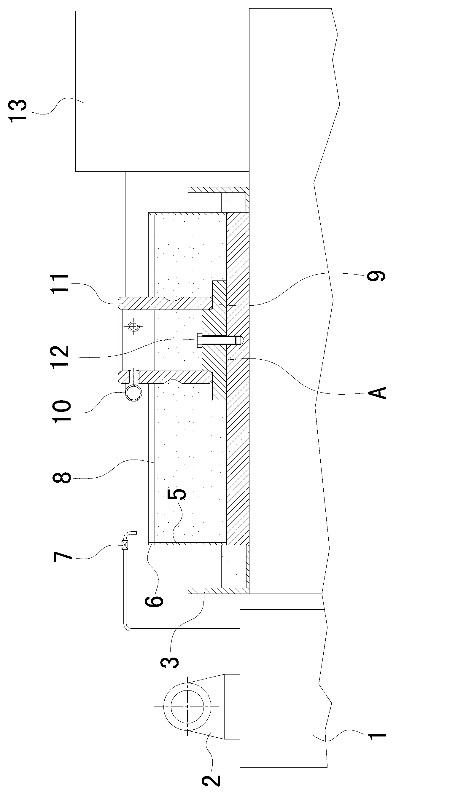
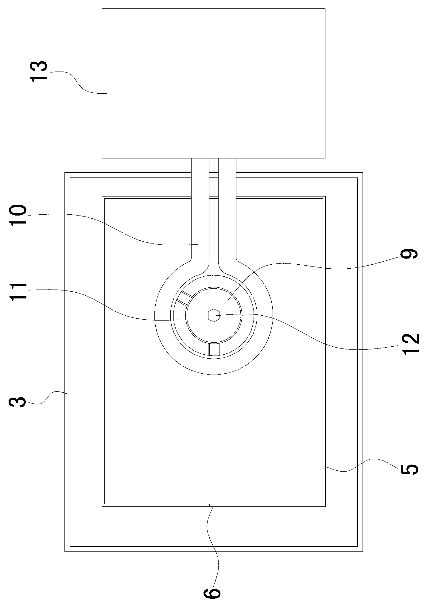
[0016] see figure 1 , 2 , a local annealing device for bearing rings, including a high-frequency induction heater 13, the high-frequency induction heater 13 has an annular heating tube 10. The device also includes a cooling water tank 5, a backflow tank 3 and a cooling water tank 1 with a water pump 2. The cooling water tank 1 is provided with a water adding pipe extending toward the cooling water tank 5. The wall of the cooling water tank 5 is provided with an overflow port 6, and the back flow tank 3 Located downstream of the overflow port 6, a return pipe (not shown in the figure) is provided between the return tank 3 and the cooling water tank 1, and the station A for clamping the bearing ring 11 is provided in the cooling water pool 5, and the annular heating pipe 10 The arc part of the is located directly above the station.

...


PUM


Abstract

The invention relates to machining equipment and a machining method of a bearing sleeve ring. The machining equipment comprises a high-frequency induction heater, wherein the high-frequency induction heater is provided with an annular heating pipe; the machining equipment further comprises a cooling water tank, a reflowing groove and a cooling water tank with a water pump; the cooling water tank is provided with a water feeding pipe; an overflowing opening is arranged on the tank wall of the cooling water tank; a water returning pipe is arranged between the reflowing groove and the cooling water tank; the cooling water tank is provided with a station for clamping the bearing sleeve ring; and a circular arc part of the annular heating pipe is located right above the station. The invention provides a rolling path protection device in a partial softening process of a screw hole; the circulating cooling water tank is arranged so that the rolling path and two proper parts of the two sides of the rolling path are immersed into cooling water when a sleeve ring screw hole and the periphery are heated and softened at a required high temperature; and a liquid surface of the cooling water tank is used for separating the bearing sleeve ring into a heating region containing the screw hole and a cooling region containing the rolling path, so as to effectively relieve the heat conduction speed of a heated part to the rolling path, and guarantee that the hardness of the rolling path is not influenced in a whole partial softening process.

Description

technical field [0001] The invention relates to a bearing ring processing equipment and processing method, in particular to a local annealing device and annealing method for a bearing ring with a screw hole. Background technique [0002] Wide inner ring bearing with set screws on the inner ring. There are at least 2 radial threaded holes in the inner ring near the end of the bearing raceway. The set screws matching the threaded holes can be used to fix the bearing on the shaft, which is easy to install It is widely used in textile, agricultural machinery, conveying and engineering machinery and other fields for use, maintenance and main engine repair. [0003] For bearing rings with screw holes made of high carbon steel, the upper screw holes are usually processed before heat treatment and quenched together with the workpiece (bearing ring) to about HRC60. During the process of tightening the set screw, due to the high hardness of the screw hole, the cracks of the screw tee...

Claims


Application Information

Patent Timeline
IPC IPC(8): C21D9/40C21D1/26
Inventor 陈庆熙田文军陈太平王冰王国荣
Owner 中山市盈科轴承制造有限公司
Learn More