Soot blocking pipe bundle of steam injection boiler for burning residual oil with high silt content

A steam injection boiler and ash tube technology, which is applied in the combustion method, combustion product treatment, and solid residue removal, etc., can solve problems such as the decline of boiler output and thermal efficiency, affecting the normal operation of the boiler, and the dense arrangement of convection tube bundles. The effect of reducing the concentration of fly ash, improving the recovery rate of heavy oil and increasing the convective heating surface

Active Publication Date: 2013-04-03
山东茵温特节能环保科技有限公司
View PDF5 Cites 2 Cited by
  • Summary
  • Abstract
  • Description
  • Claims
  • Application Information

AI Technical Summary

Problems solved by technology

After the boiler has been in operation for a long time, the cohesive ash accumulation in the convection section will reduce the output and thermal efficiency of the boiler, affecting the normal operation of the boiler
The furnace has to be shut down frequently for manual dust cleaning. Not only is the environment harsh, but it is also difficult to clean up the dust accumulation due to the dense arrangement of convection tube bundles.

Method used


Image

  • Soot blocking pipe bundle of steam injection boiler for burning residual oil with high silt content
  • Soot blocking pipe bundle of steam injection boiler for burning residual oil with high silt content
  • Soot blocking pipe bundle of steam injection boiler for burning residual oil with high silt content

Examples


Embodiment Construction

[0027] The structure of the present invention will be described in detail below in conjunction with the drawings and specific embodiments.

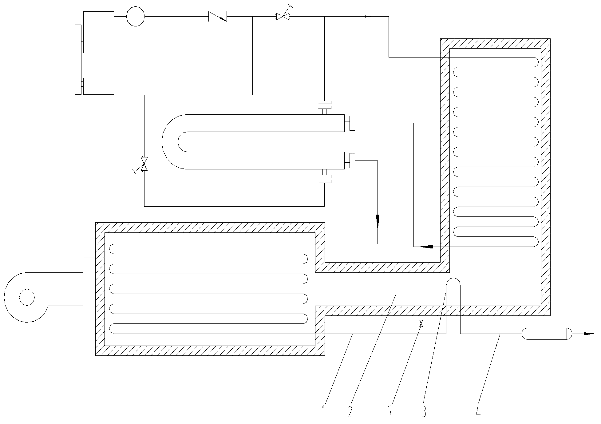
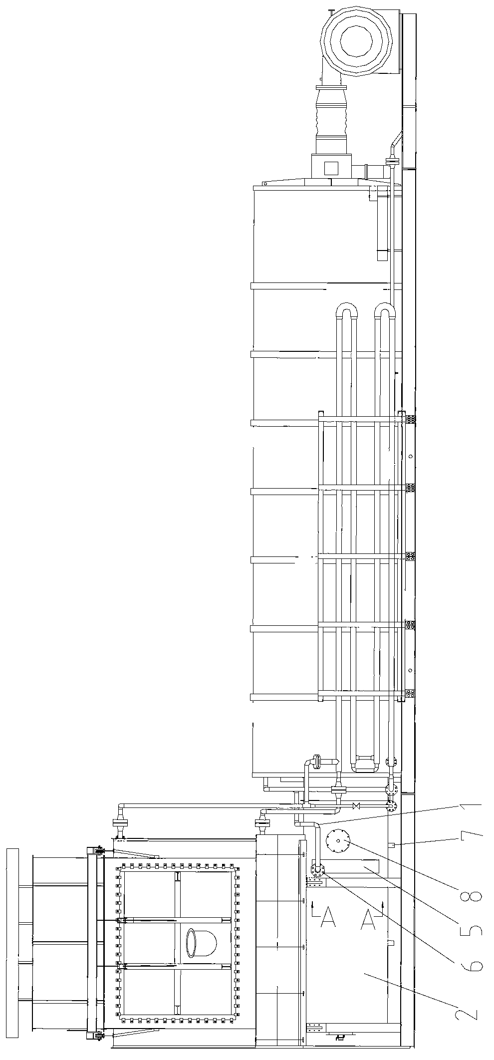
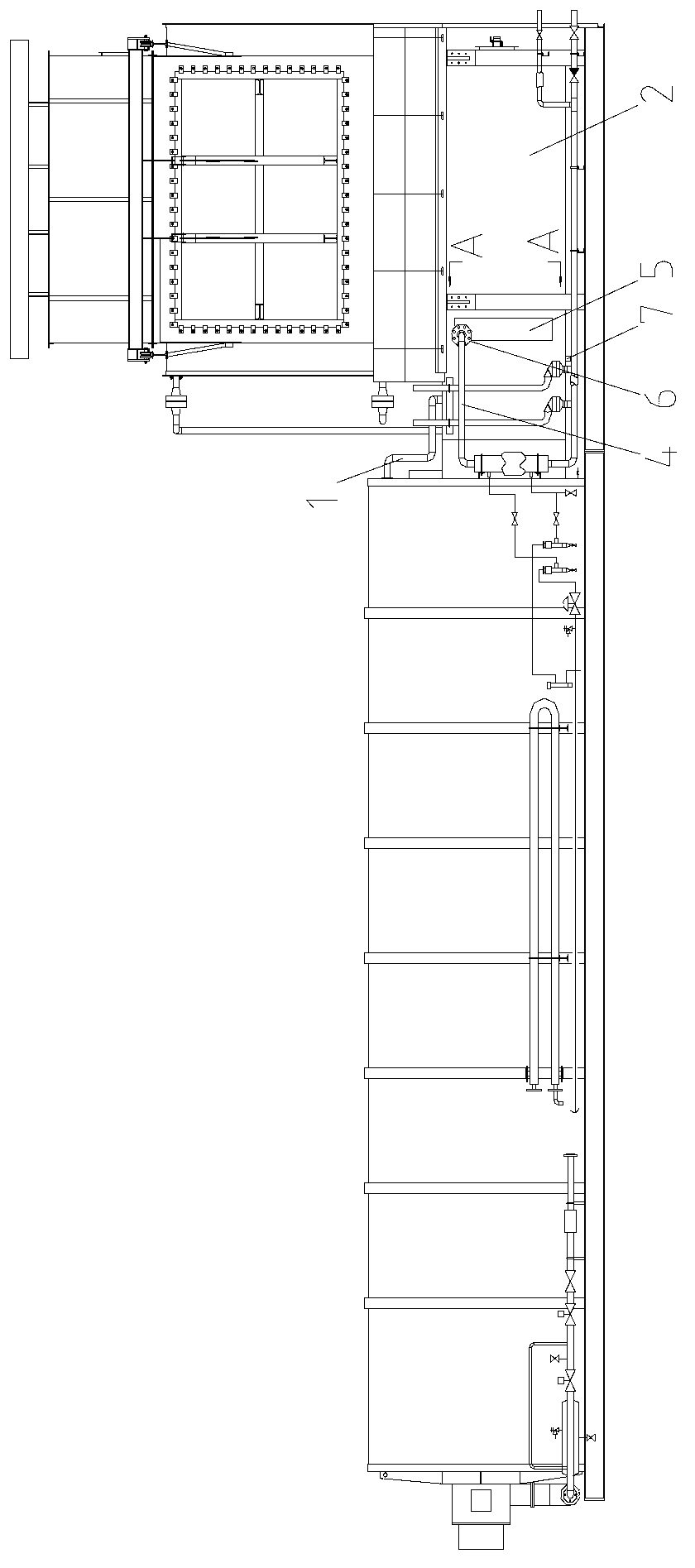
[0028] Such as figure 1 , figure 2 and image 3 As shown, the present invention is a kind of ash-retaining tube bundle used for burning residual oil steam injection boilers containing more sediment, including ash-retaining tube bundle 3, and ash-retaining tube bundle 3 is respectively connected to the inlet pipe of the ash-retaining pipe through flanges 6 at both ends. 1 is connected to the outlet pipeline 4 of the ash-retaining pipe, the inlet pipe 1 of the ash-retaining pipe is connected to the outlet of the radiation pipe, the outlet pipe 4 of the ash-retaining pipe is connected to the inlet of the steam sampling separator, and also includes a transition section 2 arranged in front of the ash-retaining pipe bundle 3 The upper soot blower 8 and the ash discharge hole 7 at the bottom of the transition section 2. The ash-retaining tub...


PUM


Abstract

The invention discloses a soot blocking pipe bundle of a steam injection boiler for burning residual oil with high silt content, which comprises soot blocking pipe bundles, a soot blower and a soot exhaust hole, wherein the soot blocking pipe bundles are connected with a soot blocking pipe inlet pipeline and a soot blocking pipe outlet pipeline respectively through flanges at the two ends of the soot blocking pipe bundles; the soot blocking pipe inlet pipeline is connected with a radiation pipe bundle outlet; the soot blocking pipe outlet pipeline is connected with a steam sampling separator inlet; the soot blower is arranged in front of the soot blocking pipe bundles; the soot exhaust hole is formed in the bottom of a transition section; the soot blocking pipe bundles are arranged at the corners of the L-shaped transition sections of the steam injection boiler; straight pipes are arranged in a reciprocating way, and are connected with one another by using elbows; the elbows are arranged in pipe boxes of soot blocking pipes on both sides of the soot blocking pipe bundles; two rows of soot blocking pipe bundles are arranged; pipe banks are arranged vertically; the straight pipes are arranged horizontally; and two rows of pipes are arranged in a staggered way. Most musky coal and large-particle dust in flue gas can be prevented from moving and are deposited at the bottom of the transition section, and molten compounds and most residual flying ash in flue gas can be adsorbed, so that the concentration of flying ash in flue gas at a countercurrent section is lowered, the amount of loose soot accumulated in countercurrent pipe bundles is very small, soot is easy to clear, and normal heat exchange is ensured.

Description

technical field [0001] The invention relates to an ash retaining tube bundle suitable for fuel oil steam injection boilers, especially for burning residual oil steam injection boilers containing a lot of sediment. Background technique [0002] Steam injection boiler is an important equipment for mining heavy oil. The high-temperature and high-pressure saturated steam generated by the boiler is injected into the oil well to increase the temperature of the heavy oil and reduce the viscosity, making it easy to mine. The steam injection boiler consists of a radiation section, a transition section, a convection section, a water-water heat exchanger and connecting pipes. Due to the increase in crude oil demand and the increase in crude oil prices, steam injection boilers generally use residual oil instead of crude oil as fuel. Residual oil is the residual oil obtained from vacuum distillation in the refining process. Impurities such as sediment and metal compounds in crude oil re...

Claims


Application Information

Patent Timeline
Patent Type & Authority Applications(China)
IPC IPC(8): F23J3/04
Inventor 吴东垠曹慎腾赵若焱邹洋蒙佳王利兵
Owner 山东茵温特节能环保科技有限公司
Why Eureka
Try Eureka