
Measuring method for damage layer thickness of optical material subsurface

A technology of subsurface damage and optical materials, which is applied in measurement devices, preparation of test samples, instruments, etc., can solve the problem that the test accuracy is greatly affected, the experimental results are greatly affected, and the test accuracy of chemical etching solution differential corrosion method is not easy. Guarantee and other issues, to achieve the effect of low test cost, simple sample preparation process and suitable for large-scale promotion

Active Publication Date: 2015-04-29
NANJING UNIV OF AERONAUTICS & ASTRONAUTICS
View PDF5 Cites 3 Cited by
  • Summary
  • Abstract
  • Description
  • Claims
  • Application Information

AI Technical Summary

Problems solved by technology

[0003] The test accuracy of chemical corrosion liquid differential corrosion method is not easy to guarantee, and the test environment factors and the test accuracy of test instruments have a great influence on the test results
The measurement of subsurface damage by magnetorheological polishing spot method does not take the metamorphic layer into account, so the measurement of the depth of the crack layer cannot fully meet the needs of reflecting the actual situation. Greater impact

Method used


Image

  • Measuring method for damage layer thickness of optical material subsurface
  • Measuring method for damage layer thickness of optical material subsurface
  • Measuring method for damage layer thickness of optical material subsurface

Examples


Embodiment Construction

[0030] The present invention will be further described below in conjunction with the accompanying drawings and embodiments.

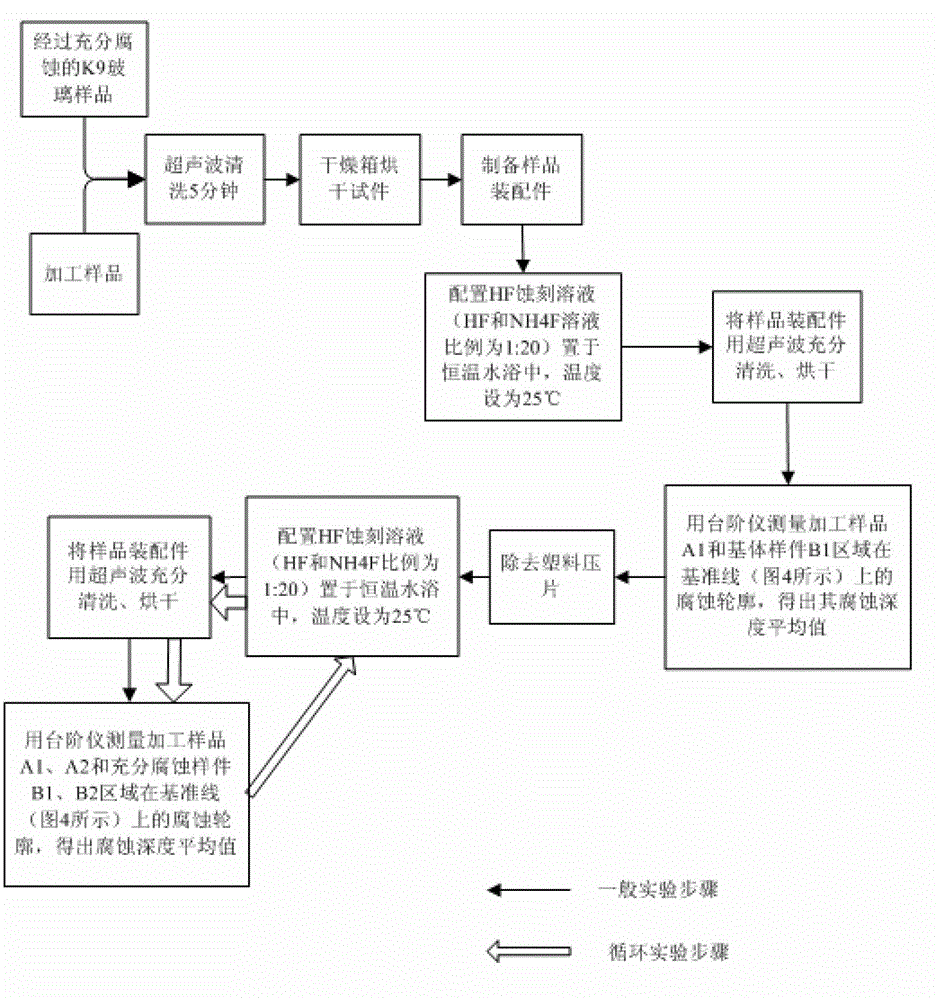
[0031] A method for measuring the thickness of a subsurface damaged layer of a hard and brittle optical material, comprising the steps of:

[0032] (1) Configure the chemical etching solution, and place the container containing the chemical etching solution in a constant temperature environment; place the substrate sample in the etching solution for no less than 2 hours to ensure that the subsurface damage layer has been completely removed, and obtain the results for comparison The substrate sample used;

[0033] (2) Put the processed sample to be tested with the same length and width and the substrate sample that has been fully corroded in the first step into the ultrasonic cleaning machine for cleaning at the same time or separately, take it out, and put it in a drying oven for drying;

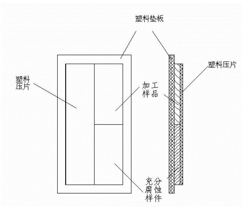
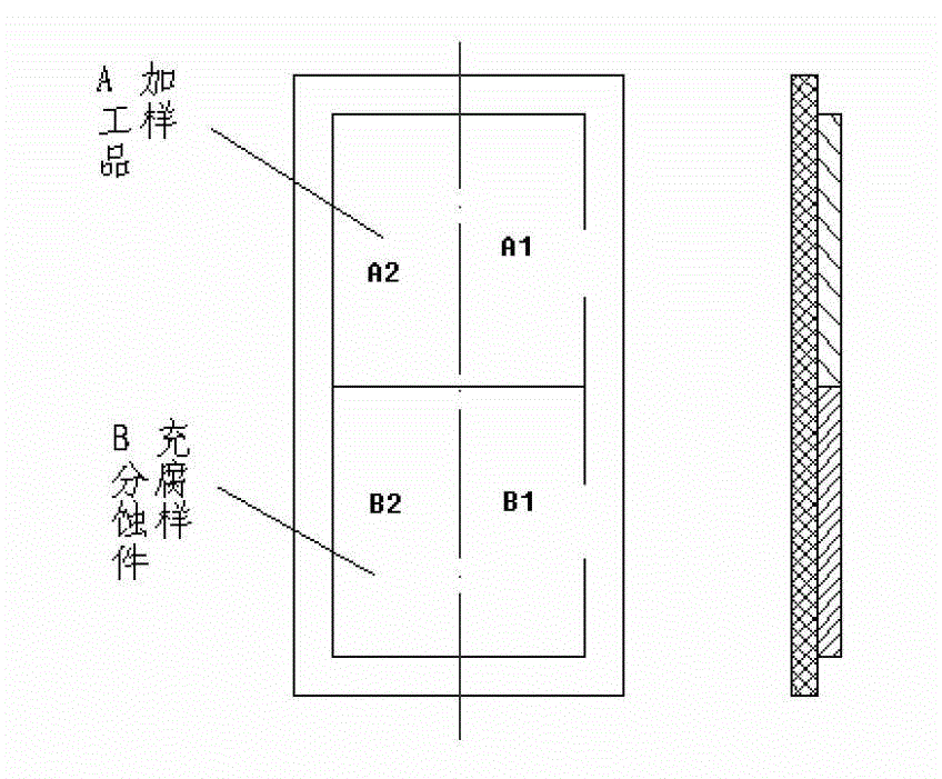
[0034] (3) Prepare the sample assembly; attach the cleaned and ...


PUM


Abstract

The invention relates to the technical field of optical precision measurements, particularly relates to a method for measuring a damage layer thickness of a hard brittle optical material subsurface. The method for measuring the damage layer thickness of the hard brittle optical material subsurface utilizes the corrosivity of HF acid to corrode processing samples and base body samples (referring to work pieces which have been completely eliminated the surface damages) under the same conditions, meanwhile marks the corrosion time and the corrosion operation sequence in segmentation. If starting from the n+1 time period, the corrosion rate of the processing samples is equal to that of the base body samples, and then the processing samples can be considered to be corroded to the base body, and to effectively reducing the experiment error accumulation caused by experimental environment factors or multi-step repeated operations, a correction factor Ki is introduced, the corresponding accumulation corrosion depth in n time periods is the damage layer thickness of the surface. The method for measuring the damage layer thickness of the hard brittle optical material subsurface has the advantages of being simple and quick in measuring process, high in measuring accuracy, and low in the requirement for measuring equipment.

Description

technical field [0001] The invention relates to the technical field of optical precision measurement, in particular to a method for measuring the thickness of a subsurface damaged layer of a hard and brittle optical material, specifically a method that introduces a correction factor that can improve measurement accuracy and eliminate environmental factors and human factors for measurement. Accuracy-influenced methods for measuring thickness of subsurface damaged layers in optical materials. Background technique [0002] Since the 1970s, many scientists at home and abroad have carried out research on the subsurface damage evaluation technology of optical workpieces. At present, the subsurface damage evaluation methods mainly include chemical corrosion solution differential corrosion method, angle polishing method, magnetorheological polishing spot method, cross-section microscopy method and so on. Magnetorheological polishing spot method to measure subsurface damage is to fo...

Claims


Application Information

Patent Timeline
Patent Type & Authority Patents(China)
IPC IPC(8): G01B21/08G01N1/32
Inventor 朱永伟戴子华刘婷婷李军左敦稳
Owner NANJING UNIV OF AERONAUTICS & ASTRONAUTICS
Learn More