Dual-channel common-path prism dispersion broadband imaging spectrometer optical system

An imaging spectrometer and optical system technology, applied in the field of space optics, can solve the problems of large volume and weight, complex structure of broadband imaging spectrometer, etc., and achieve the effect of compact system layout and high spectral transmission efficiency

Inactive Publication Date: 2013-04-03
CHANGCHUN INST OF OPTICS FINE MECHANICS & PHYSICS CHINESE ACAD OF SCI
View PDF2 Cites 10 Cited by
  • Summary
  • Abstract
  • Description
  • Claims
  • Application Information

AI Technical Summary

Problems solved by technology

[0003] In order to solve the problems of complex structure, large volume and heavy weight of the existing broadband imaging spectrometer

Method used


Image

  • Dual-channel common-path prism dispersion broadband imaging spectrometer optical system
  • Dual-channel common-path prism dispersion broadband imaging spectrometer optical system

Examples


specific Embodiment approach 1

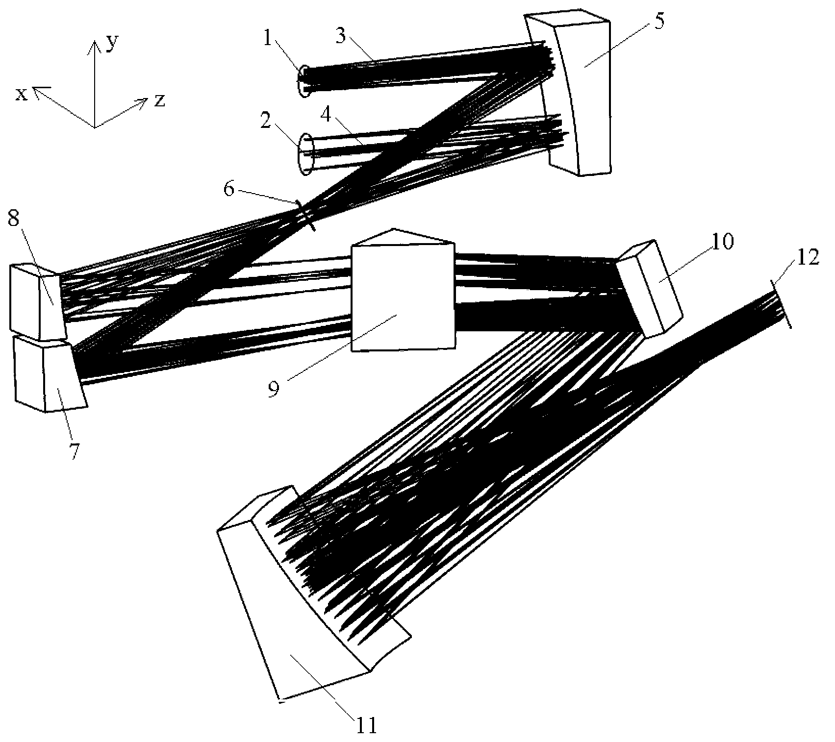
[0010] Specific implementation mode 1. Combination figure 1 with figure 2 Describe this embodiment, the optical system of a dual-channel common optical path prism dispersion broadband imaging spectrometer, the optical system includes a first aperture stop 1, a second aperture stop 2, a telescope 5, an entrance slit 6, and a first collimating mirror 7 , the second collimating mirror 8, the dispersion prism 9, the first imaging mirror 10, the second imaging mirror 11 and the detector image plane 12; The first channel 3 and the second channel 4 are respectively incident on the same telescope 5, imaged on the incident slit 6 by the telescope 5, and after exiting from the incident slit 6, pass through the first collimating mirror 7 and the second collimating mirror respectively 8, incident on the dispersion prism 9, incident on the first imaging mirror 10 after being dispersed by the dispersion prism 9, incident on the second imaging mirror 11 after being reflected by the first i...

specific Embodiment approach 2

[0013] Specific embodiment two, this embodiment is the application of the dual-channel co-optical path prism dispersion wide-band imaging spectrometer optical system described in specific embodiment one, this embodiment detects the atmospheric ozone profile in a limbo observation mode, and the orbital height H =833km, the distance from the instrument to the limb observation point is 3365km, the spectral resolution is 1.5nm-40nm, and the spatial resolution is 3km. The focal length of the optical system of the imaging spectrometer is 69mm, the field of view is 2.3°×0.034°, and the working band is 280-1000nm. Atmospheric limb scenes are incident on the same telescope 5 through the first aperture stop 1 and the second aperture stop 2 into a first channel 3 and a second channel 4 . The aperture of the first aperture stop 1 is 6mm, and the aperture of the second aperture stop 2 is 10mm. The large aperture is used for weak signal detection, and the small aperture is used for strong s...


PUM

PropertyMeasurementUnit
Caliberaaaaaaaaaa
Caliberaaaaaaaaaa

Abstract

The invention discloses a dual-channel common-path prism dispersion broadband imaging spectrometer optical system, and relates to the technical field of space optics, aiming at solving the problems of complex structure, large volume and heavy weight of the existing broadband imaging spectrometer optical system. The dual-channel common-path prism dispersion broadband imaging spectrometer optical system comprises a first aperture diaphragm, a second aperture diaphragm, a telescope, an entrance slit, a first collimating mirror, a second collimating mirror, a dispersion prism, a first imaging mirror, a second imaging mirror and a detector image plane; light beams emitted by a same objective, passing through the first aperture diaphragm and the second aperture diaphragm, are respectively reflected onto the telescope through a first channel and a second channel, imaged on the entrance slit through the telescope, reflected onto the dispersion prism through the first collimating mirror and the second collimating mirror, dispersed by the dispersion prism, and are imaged on the detector image plane through the first imaging mirror and the second imaging mirror. The optical system disclosed by the invention is applicable to aeronautic and astronautic atmospheric remote sensing, earth observation and other fields.

Description

technical field [0001] The invention relates to the technical field of space optics, in particular to a reflective prism dispersion broadband imaging spectrometer optical system in space optics. Background technique [0002] Imaging spectrometer is a new type of space optical remote sensing instrument developed on the basis of multispectral remote sensing technology. It can obtain super multispectral images of targets with high spectral resolution. The wider the application. In recent years, with the continuous development of space remote sensing applications, the requirements for the band range and dynamic range of imaging spectrometers are also getting higher and higher. The band range has been extended from the usual visible band to the ultraviolet band. The wider the band, the richer the spectral information of the target contained. It is necessary to realize the simultaneous detection of wide-band signals from ultraviolet to visible. In the field of wide-band atmosphe...

Claims


Application Information

Patent Timeline
IPC IPC(8): G01J3/02
Inventor 薛庆生王淑荣
Owner CHANGCHUN INST OF OPTICS FINE MECHANICS & PHYSICS CHINESE ACAD OF SCI
Why Eureka
Try Eureka