
Optical racemization and slit scanning integrated device based on solar telescope grating spectrometer

A technology for solar telescopes and grating spectrometers, applied in the field of optical derotation and slit scanning integrated devices, which can solve the problems of many optical components, large space occupation, and complex control systems

Active Publication Date: 2013-04-03
INST OF OPTICS & ELECTRONICS - CHINESE ACAD OF SCI
View PDF3 Cites 16 Cited by
  • Summary
  • Abstract
  • Description
  • Claims
  • Application Information

AI Technical Summary

Problems solved by technology

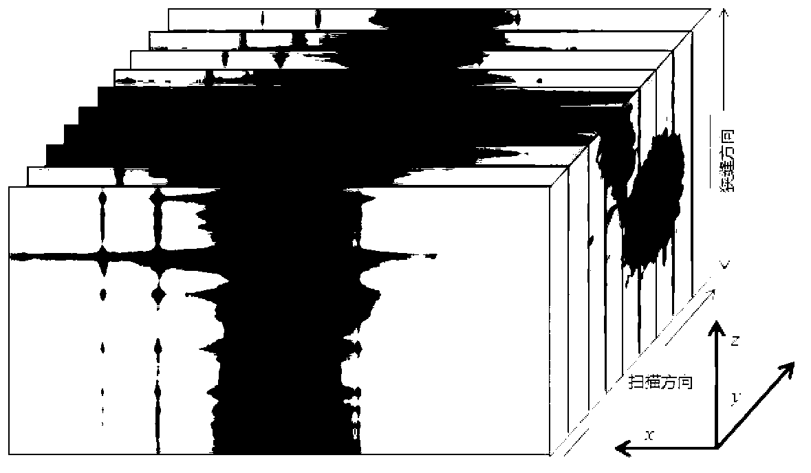
[0006] The technical problem to be solved by the present invention is: the optical derotation and the slit scanning mechanism of the solar telescope grating spectrometer are independent of each other in the traditional ground-level rack structure, and many optical components are used, which has a great impact on the imaging quality of the optical system and takes up space. Large size, complex control system and other problems, a kind of optical derotation and slit scanning integrated device based on solar telescope grating spectrometer is proposed, trying to realize optical derotation at the same time with the least optical components, the most compact optical structure, and the simplest control scheme and the function of slit scanning

Method used


Image

  • Optical racemization and slit scanning integrated device based on solar telescope grating spectrometer
  • Optical racemization and slit scanning integrated device based on solar telescope grating spectrometer
  • Optical racemization and slit scanning integrated device based on solar telescope grating spectrometer

Examples


Embodiment Construction

[0046] The present invention will be further described below in conjunction with the accompanying drawings and specific embodiments.

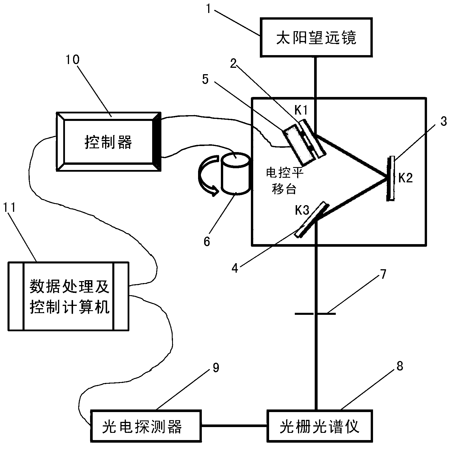
[0047] Optical derotation and slit scanning integrated device based on solar telescope grating spectrometer, including solar telescope 1, K1 plane mirror 2, K2 plane mirror 3, K3 plane mirror 4, electronically controlled translation platform 5, electronically controlled rotary platform 6. Grating spectrometer slit 7, grating spectrometer 8, photodetector 9, controller 10 and data processing and control computer 11. The slit 7 of the grating spectrometer is located on the focal plane of Coude of the solar telescope. Since the image on the focal point of Coude is constantly rotating and changing during the process of tracking the active region of the sun, the spectral scanning observation of a certain active region on the sun or in the spectral When the observation needs to be exposed for a long time, it is necessary to use optical derotation to ...


PUM


Abstract

The invention relates to an optical racemization and slit scanning integrated device based on a solar telescope grating spectrometer. The optical racemization and slit scanning integrated device comprises a solar telescope (1), a K1 plane mirror (2), a K2 plane mirror (3), a K3 plane mirror (4), an electrical control translation stage (5), an electrical control rotating platform (6), a grating spectrometer slit (7), a grating spectrometer (8), a photoelectric detector (9), a controller (10) and a data processing and control computer (11). At present, most of solar telescopes use horizontal type rack structures, image field rotation problems are easily caused in the object tracking process by means of the structures, so that on one hand, a special image field racemization device is required to be equipped, and on the other hand, a special slit scanning device is required to be equipped to obtain three-dimensional information of a solar activity region. The optical racemization and slit scanning integrated device is simple in structure, small in occupied space, few in optical mirror planes and high in innovativeness and practicality.

Description

technical field [0001] The invention relates to the technical field of optical derotation and slit scanning devices for solar telescope grating spectrometers, in particular to an integrated device for optical derotation and slit scanning based on solar telescope grating spectrometers. Background technique [0002] The ground-level rack structure has obvious mechanical advantages, and the installation location of the solar telescope adopting this structure has nothing to do with the geographical latitude. At present, most of the solar telescopes in the world adopt this structure, especially the large aperture solar telescopes. Horizontal solar telescopes will generate image rotation when tracking and observing local areas of the sun's surface, that is, the observation target in the field of view will rotate around the center of the visual axis, which will bring image consistency to the solar telescope and image processing algorithms based on multi-frame accumulation. caused ...

Claims


Application Information

Patent Timeline
Patent Type & Authority Applications(China)
IPC IPC(8): G01J3/28G01J3/02
Inventor 顾乃庭饶长辉刘洋毅郑联慧朱磊张兰强钟立波
Owner INST OF OPTICS & ELECTRONICS - CHINESE ACAD OF SCI
Learn More