High-precision large-caliber electric reflecting mirror frame based on orthogonal axis

A reflective mirror frame, high-precision technology, applied in installation, optics, instruments, etc., can solve the problems of poor beam flexibility, inaccuracy, and difficult control of laser beams, improve repeat positioning accuracy and stability, and realize two-dimensional angles Effect of adjustment, reduction of deformation and installation error

Inactive Publication Date: 2013-04-03
HARBIN INST OF TECH
View PDF7 Cites 41 Cited by
  • Summary
  • Abstract
  • Description
  • Claims
  • Application Information

AI Technical Summary

Problems solved by technology

[0003] The purpose of the present invention is to provide a high-precision large-diameter electric mirror frame based on an orthogonal axis system to solve the problem that the process of guiding the transmission dire

Method used


Image

  • High-precision large-caliber electric reflecting mirror frame based on orthogonal axis
  • High-precision large-caliber electric reflecting mirror frame based on orthogonal axis
  • High-precision large-caliber electric reflecting mirror frame based on orthogonal axis

Examples


specific Embodiment approach 1

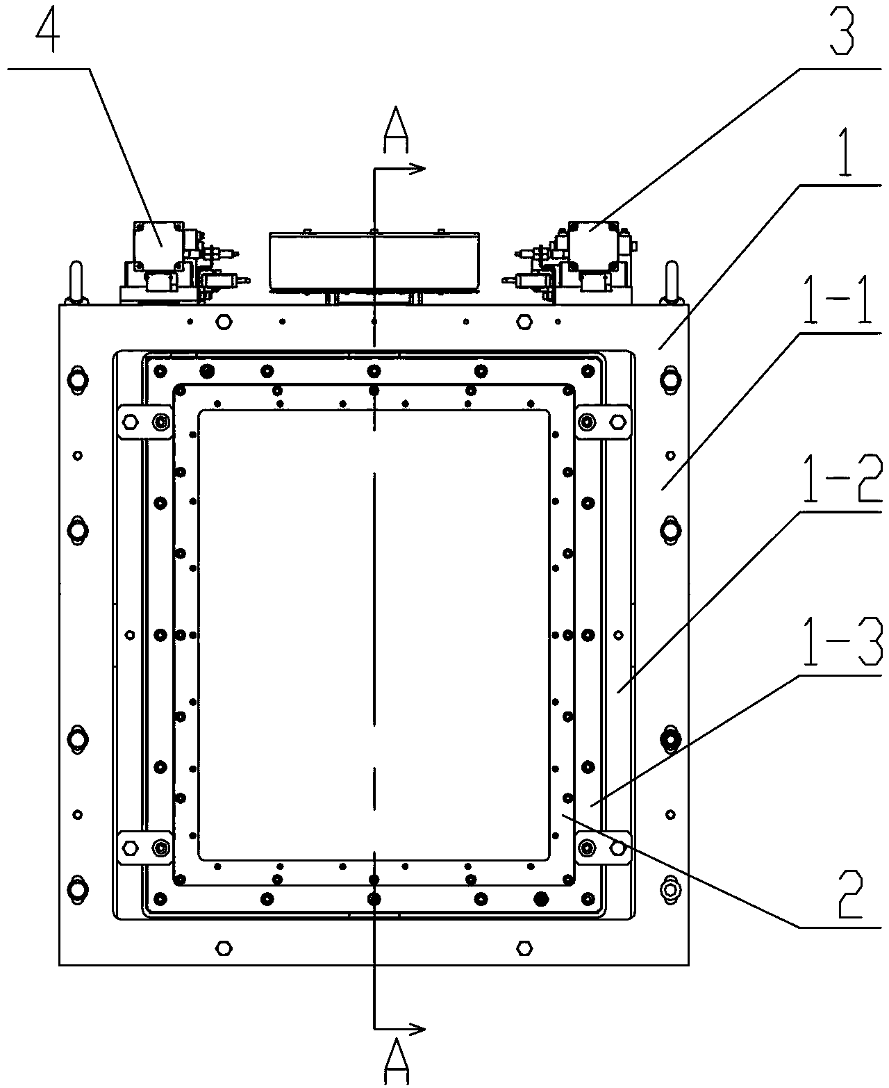
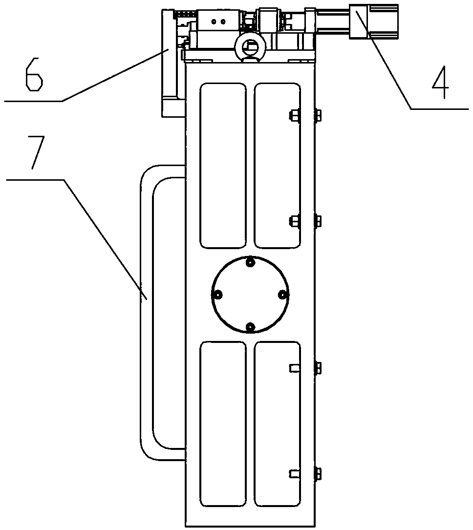
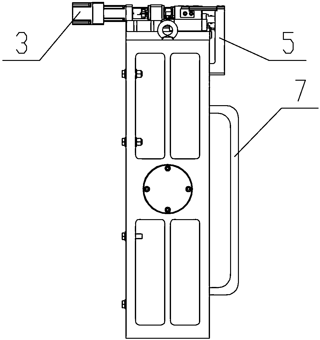
[0014] Specific implementation mode one: combine Figure 1 to Figure 14 Describe this embodiment, the high-precision large-diameter motorized mirror frame in this embodiment includes a mirror frame base assembly 1, a transition frame assembly 2, two micro-drivers, a pitch connection block 5 and a yaw connection block 6, two The three micro-drivers are pitch axis micro-driver 3 and yaw-axis micro-driver 4 respectively. The rotating shaft 1-4, two second rotating shafts 1-5 and four pairs of bearings 1-6, the frame 1-1, the pitch shaft frame 1-2, and the yaw shaft frame 1-3 are all rectangular structures, and the two horizontally arranged A first rotating shaft 1-4 passes through two vertical frames of the frame 1-1, and the frame 1-1 establishes a connection relationship with the pitch axis frame 1-2 through the first rotating shaft 1-4, each first A pair of bearings 1-6 is arranged between the rotating shaft 1-4 and the frame 1-1, the pitching axis frame 1-2 is adjusted for t...

specific Embodiment approach 2

[0016] Specific implementation mode two: combination figure 1 , figure 2 and Figure 8 This embodiment will be described. In this embodiment, the bearings 1-6 are high-precision angular contact ball bearings. Bearings arranged in this way enable the invention of the present invention to be most effective. Two high-precision angular contact ball bearings are arranged at the ends of the first rotating shaft 1-4 and the second rotating shaft 1-5 to cooperate with each other, which not only realizes the positioning and pre-tightening of the bearings, but also reduces the impact of the pre-tightening force on the shaft frame. Deformation and installation errors.

[0017] For two pairs of bearings in the horizontal shaft system, one pair of bearings is arranged face-to-face, and the other pair of bearings is arranged back-to-back; for two pairs of bearings in the vertical shaft system, one pair of bearings is arranged face-to-face, and the other pair of bearings is arranged back...

specific Embodiment approach 3

[0019] Specific implementation mode three: combination figure 1 This embodiment will be described. In this embodiment, the pitch-axis micro-driver 3 and the yaw-axis micro-driver 4 are arranged symmetrically with respect to the vertical centerline of the mirror frame base assembly 1 . Other compositions and connections are the same as those in Embodiment 1 or 2.


PUM


Abstract

The invention discloses a high-precision large-caliber electric reflecting mirror frame based on an orthogonal axis, relates to an electric reflecting mirror frame, and aims to solve the problems that the process of guiding the transmission direction of a large-caliber laser beam is not precise enough and is not easily controlled, and collimated guide and near-field adjustment for the laser beam are poor in flexibility. A rack is connected with a pitching shaft frame through a rotation shaft, the pitching shaft frame is used for adjusting pitching angles relative to the rack, the pitching shaft frame and the rotation shaft are connected with a deflection shaft frame, the deflection shaft frame is used for adjusting deflection relative to the pitching shaft frame, a transverse positioning barrier strip is close to the inner side surface of a transition frame, an axial positioning barrier strip is close to the inner side surface of a second positioning frame, a mini-driver output end of a pitching shaft micro-actuator is connected with the pitching shaft frame through a pitching connection block, and a mini-driver output end of a deflection shaft micro-actuator is connected with the deflection shaft frame through a deflection connection block. The high-precision large-caliber electric reflecting mirror frame is used for a light beam guide system of an inertial confinement laser fusion device or other optical path adjustment systems needing large calibers.

Description

technical field [0001] The invention relates to an electric mirror frame, in particular to a high-precision large-diameter electric mirror frame based on an orthogonal shaft system. It is a precise electronically controlled mechanical adjustment mechanism and is mainly used in large-diameter laser light paths in precision optics. adjustment. Background technique [0002] The large-diameter motorized mirror holder is a precision electromechanical device for adjusting the optical path of high-energy lasers with a diameter of 400mm-600mm. At present, in the technical field related to laser nuclear fusion, there is no motorized mirror frame that can guide the transmission direction of a large-diameter laser beam with a diameter of more than 400mm with high precision. The known traditional mirror frame has low adjustment accuracy and is difficult to control. For The collimation guidance of the beam and the flexibility of the near-field adjustment of the beam are poor. It is not...

Claims


Application Information

Patent Timeline
IPC IPC(8): G02B7/198
Inventor 张宏志梁迎春胡富强张鹏
Owner HARBIN INST OF TECH
Why Eureka
Try Eureka