Device and method for controlling bias voltage of electrooptical modulator

An electro-optical modulator and bias control technology, applied in control/adjustment systems, optics, instruments, etc., can solve the problems of electro-optical modulator operating point drift, etc., and achieve the effect of improving response speed and control accuracy

Inactive Publication Date: 2013-04-03
CHINA JILIANG UNIV
View PDF4 Cites 36 Cited by
  • Summary
  • Abstract
  • Description
  • Claims
  • Application Information

AI Technical Summary

Problems solved by technology

[0005] Technical problem: The technical problem solved by the present invention is to provide an electro-optic modulator bias control device and method, which can co...

Method used


Image

  • Device and method for controlling bias voltage of electrooptical modulator
  • Device and method for controlling bias voltage of electrooptical modulator
  • Device and method for controlling bias voltage of electrooptical modulator

Examples


Embodiment Construction

[0016] The present invention is described in detail below in conjunction with example, but should not limit protection scope of the present invention with this.

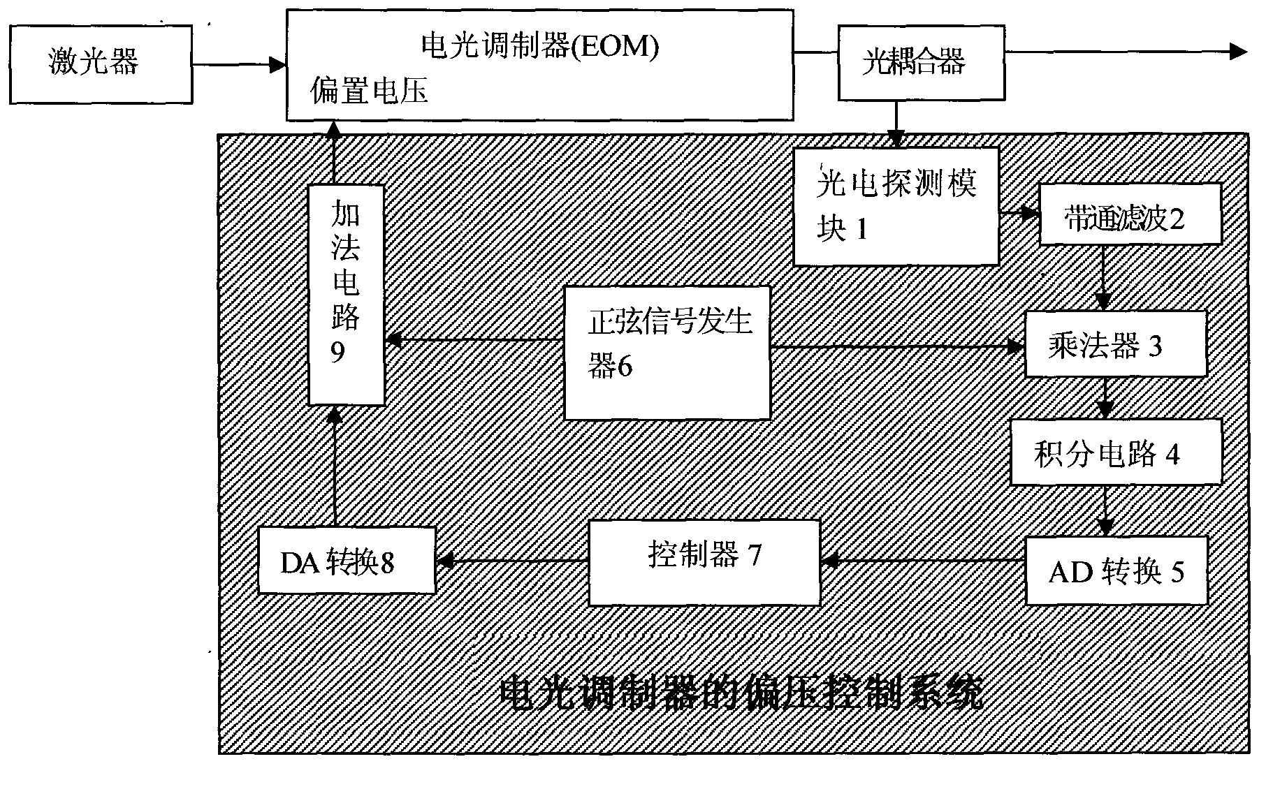
[0017] As one of the preferred solutions of the present invention, it is as follows. refer to figure 1, the device consists of a photoelectric detection module (1), a bandpass filter module (2), a multiplier module (3), an integrating circuit module (4), an analog-to-digital (AD) conversion module (5), a sinusoidal signal generator module ( 6), a controller (7), a digital-to-analog (DA) conversion module (8), and an adding circuit module (9). Its connection relation is: the output terminal of described photodetector module (1) connects the input terminal of bandpass filter (2), and the output terminal of bandpass filter (2) connects two input terminals of multiplier (3) One of them, the other input terminal of the multiplier (3) is connected to the output terminal of the sinusoidal signal generator (6), the output...


PUM


Abstract

The invention discloses a device and method for controlling the bias voltage of an electrooptical modulator. The device and method are used for controlling the bias voltage of the electrooptical modulator, not only can enable the stable working of the electrooptical modulator to resist the external interference, but also can control the electrooptical modulator to work in different states according to the need. The method comprises the following steps of: inputting a continuous-sine bias voltage signal with the known period into the electrooptical modulator, then demodulating the response of the electrooptical modulator to the signal to judge and determine the working point of the electrooptical modulator and the drift of the working point caused by external influence, and finally adjusting the bias voltage of the electrooptical modulator and enabling the electrooptical modulator to work on the set working point stably.

Description

technical field [0001] The invention relates to a bias voltage driving system of an electro-optic modulator. It is used to provide the appropriate bias voltage for the electro-optic modulator to make it work in the set working area. The invention belongs to the field of photoelectric automatic feedback control. Background technique [0002] Lithium niobate Mach-Zehnder electro-optic modulator (LiNbO 3 Mach-Zehnder Modulator) is widely used in optical communication, optical fiber sensing and other fields. Its interior consists of two identical waveguide arms and two Y-shaped branches. The input light is divided into two equal beams at the first Y branch, and then transmitted along two identical waveguide arms, and finally meet at the second Y branch and interfere. By adjusting the electric field applied to the waveguide arm, the refractive index of the waveguide crystal can be changed, so that the transmission speed of the two beams of light in the two waveguide arms is ...

Claims


Application Information

Patent Timeline
IPC IPC(8): G05F1/46G02F1/01
Inventor 李裔张彩霞张震伟马世安
Owner CHINA JILIANG UNIV
Why Eureka
Try Eureka