
Electrical fire detector based on temperature detection

An electrical fire and detector technology, applied in the field of fire detectors, can solve the problems that algorithm parameters are not easy to stabilize, the accuracy of measurement results is not high, and the constant current will change with temperature, so as to meet the accuracy requirements, suppress temperature drift, and use Safe and reliable effect

Active Publication Date: 2013-04-03
溧阳常大技术转移中心有限公司
View PDF7 Cites 8 Cited by
  • Summary
  • Abstract
  • Description
  • Claims
  • Application Information

AI Technical Summary

Problems solved by technology

This limits the frequency range of the voltage-to-current conversion circuit, so when applying a voltage-to-current conversion circuit, the required response time, linearity and drift must be met
In the existing technology, the open-loop constant current source circuit cannot overcome the temperature drift, and the constant current will change with the temperature, which is not stable enough, and the accuracy of the measurement results is not high
The closed-loop adjustment generally adopts the software method, first measures the current size, and then uses the software calculation method to change the constant current current size, the response speed is slow, and the algorithm requirements are high. If the algorithm parameters are not good, it will not be easy to stabilize.

Method used


Image

  • Electrical fire detector based on temperature detection

Examples


Embodiment Construction

[0021] The present invention is described in further detail now in conjunction with accompanying drawing. These drawings are all simplified schematic diagrams, which only illustrate the basic structure of the present invention in a schematic manner, so they only show the configurations related to the present invention.

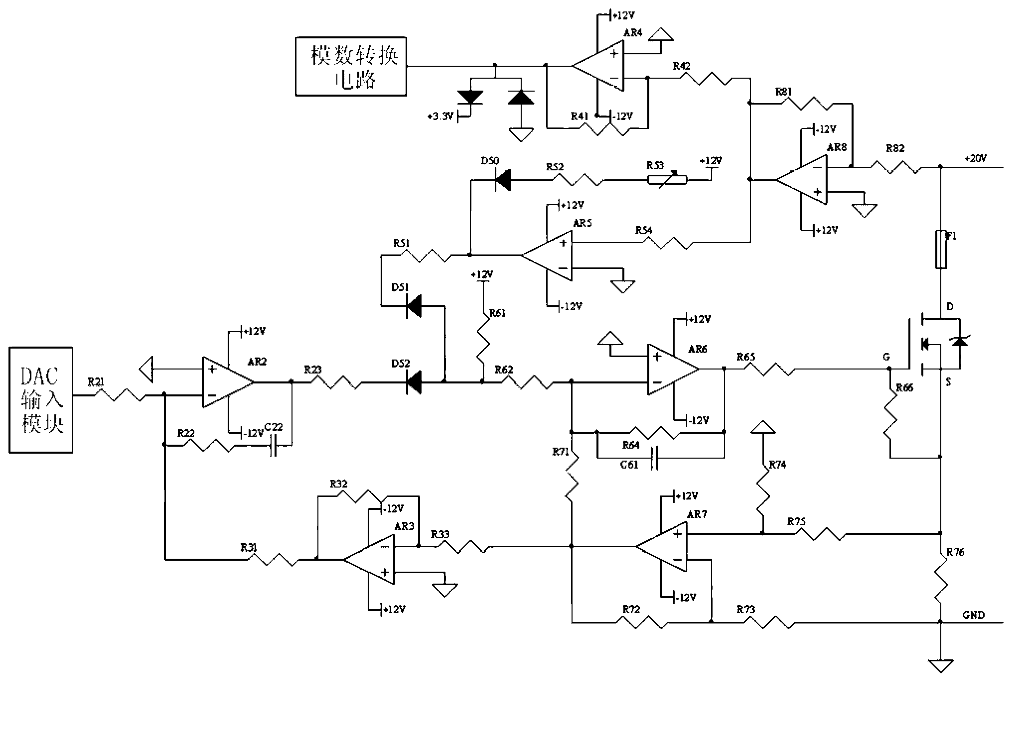
[0022] Such as figure 1 As shown, the circuit principle diagram of the optimal embodiment of the constant current source for the temperature measurement circuit in the electrical fire detector based on temperature detection of the present invention. The constant current source includes a DAC input module, a first-stage feedback circuit, a second-stage feedback circuit and a switch circuit; the first-stage feedback circuit includes a differential input operational amplifier circuit and a first reverse input adder circuit, the The second stage feedback circuit comprises a second reverse input adder circuit and a reverse amplifier circuit; the reverse input term...


PUM


Abstract

The invention relates to an electrical fire detector based on temperature detection. The electrical fire detector is provided with a constant flow source for a temperature measurement circuit, and the constant flow source comprises a digital analog converter (DAC) input module, a first summator circuit, a differential input operational amplifying circuit, a second summator circuit, a reverse amplifying circuit and a metal oxide semiconductor field effect transistor (MOSFET) switching circuit; an input end of the first summator circuit is connected with an output end of the differential input operational amplifying circuit and an output end of the second summator circuit, and an output end of the first summator circuit is connected with a grid electrode of a MOSFET; an input end of the reverse amplifying circuit is connected with the output end of the differential input operational amplifying circuit, and an output end of the reverse amplifying circuit is connected with an input end of the second summator circuit; the DAC input module is connected with the input end of the second summator circuit; and a same direction input end of the differential input operational amplifying circuit is connected with a source electrode of the MOSFET, and a reverse input end of the differential input operational amplifying circuit is grounded. According to the electrical fire detector, by means of the constant flow source for the temperature measurement circuit, four operational amplifying circuits are used for achieving double closed-loop dual feedback control, the accuracy of constant current is high, the responding speeds are high, and the generality is good.

Description

technical field [0001] The invention relates to a fire detector, in particular to an electrical fire detector based on temperature detection. Background technique [0002] With the rapid development of our country's society and economy, the demand for electricity has grown rapidly. Today, fires caused by electrical factors have remained high, causing huge losses to national property and people's lives. Electrical fires have become an important issue affecting social stability and safety. , The first major unfavorable factor that endangers people's lives and property safety. [0003] The measurement signal of the current electrical fire detector is affected by the temperature measurement circuit, the accuracy is low, the predictability of the fire is poor, and the universality of the detector is not strong, and the service life is short. [0004] Since the constant current source is relatively stable and can measure a relatively stable voltage value, the Pt100 temperature me...

Claims


Application Information

Patent Timeline
Patent Type & Authority Applications(China)
IPC IPC(8): G08B17/06G05F1/56
Inventor 王天成郑剑锋强浩
Owner 溧阳常大技术转移中心有限公司
Learn More