Protective circuit for cascade of multiple battery strings

A technology for protecting circuits and batteries, applied in the direction of emergency protection circuit devices, electrical components, etc., to achieve the effects of avoiding entry, easy protection, and overcoming voltage resistance problems

Active Publication Date: 2013-04-03
SINO WEALTH ELECTRONICS
View PDF7 Cites 4 Cited by
  • Summary
  • Abstract
  • Description
  • Claims
  • Application Information

AI Technical Summary

Problems solved by technology

[0006] To sum up, in the realization of the multi-cell battery protection scheme, especially when the total battery vol

Method used


Image

  • Protective circuit for cascade of multiple battery strings
  • Protective circuit for cascade of multiple battery strings
  • Protective circuit for cascade of multiple battery strings

Examples


Example Embodiment

[0029] The present invention will be further explained below in conjunction with specific embodiments and drawings. In the following description, more details are set forth in order to fully understand the present invention. However, the present invention can obviously be implemented in many other ways different from the description herein. Those skilled in the art can make similar promotion and deduction according to actual application conditions without violating the connotation of the present invention. Therefore, the content of this specific embodiment should not limit the protection scope of the present invention.

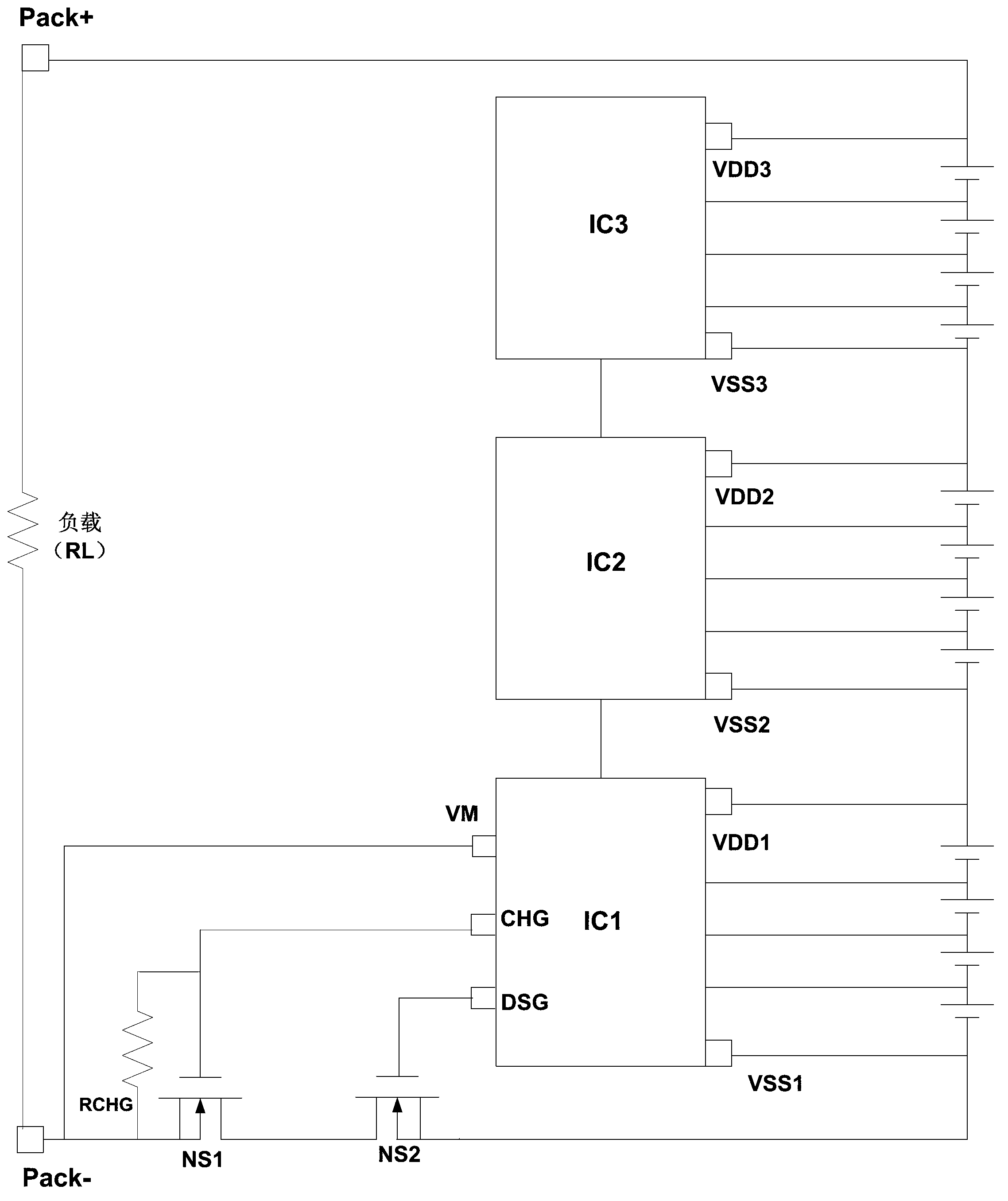
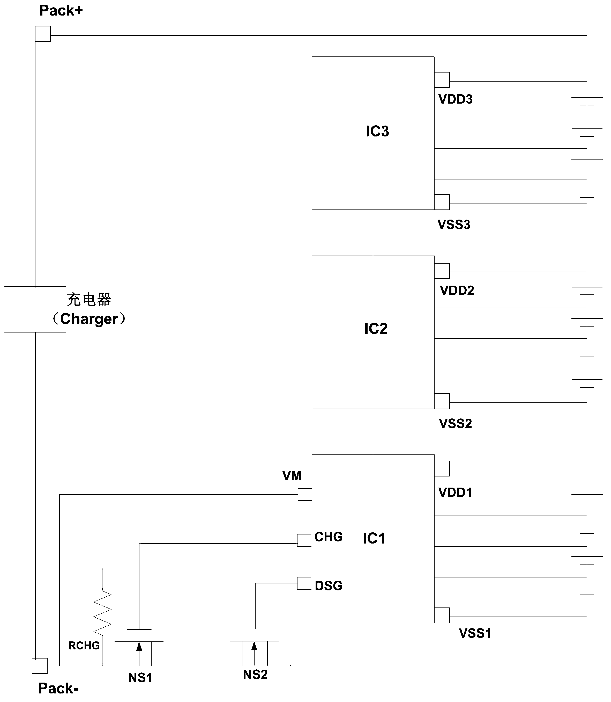
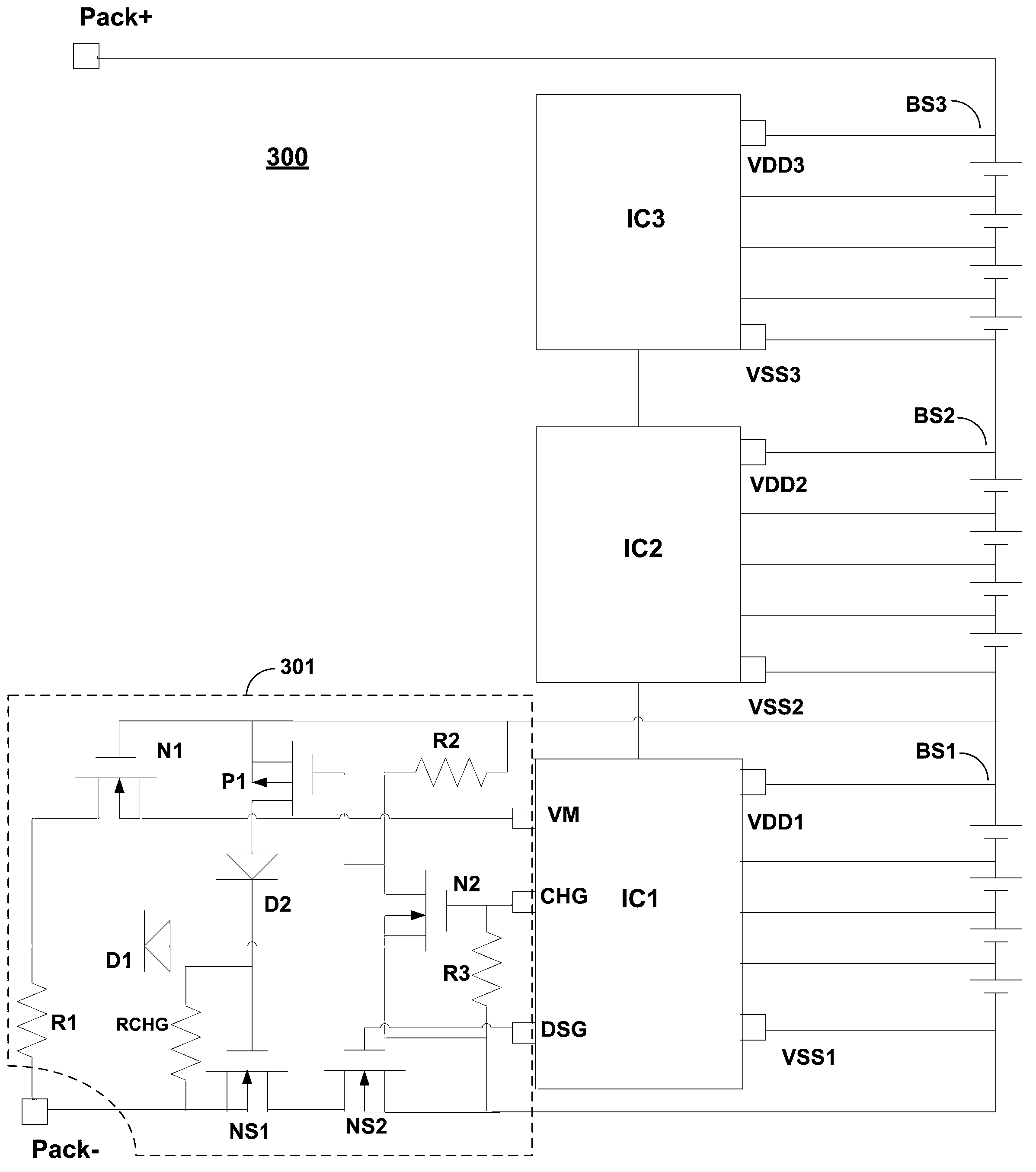
[0030] image 3 It is a schematic structural diagram of a protection circuit for cascading multiple strings of batteries according to an embodiment of the present invention. The battery can be a lithium battery for electric tools or electric bicycles, but those skilled in the art should understand that the battery can also be various batteries in other high-volta...


PUM


Abstract

The invention provides a protective circuit for cascade of multiple battery strings. The protective circuit comprises a chip port voltage withstand protection circuit. A first resistor of the chip port voltage withstand protection circuit is connected with a battery pack negative terminal and a negative terminal of a first diode. A positive terminal of the first diode is connected with a ground end. A drain terminal of a first NMOS (N-channel metal oxide semiconductor) transistor of the chip port voltage withstand protection circuit is connected with a negative terminal of the first diode, a source terminal and a substrate in the first NMOS transistor are short-circuited and are connected with a battery pack negative terminal detection end, and a gate terminal of the first NMOS transistor is connected with a power terminal. A gate end of a second NMOS transistor of the chip port voltage withstand protection circuit is connected with a control terminal of a charge tube, a source terminal and a substrate in the second NMOS transistor are short-circuited and are connected with the ground end, a drain terminal of the second NMOS transistor is connected with a second resistor, and the second resistor is connected with the power terminal. A gate terminal of a PMOS (p-channel metal oxide semiconductor) transistor of the chip port voltage withstand protection circuit is connected with the drain terminal of the second NMOS transistor, a source terminal and a substrate in the PMOS transistor are short-circuited and are connected with the power terminal, and a drain terminal of the PMOS transistor is connected with a positive terminal of a second diode. A negative terminal of the second diode is connected with a gate terminal of the charge tube. A source terminal and a substrate in the charge tube are short-circuited and are connected with a battery pack negative terminal, and a drain terminal of the charge tube is connected with a drain terminal of a discharge tube. A source terminal and a substrate in the discharge tube are short-circuited and are connected with the ground end, and a gate terminal of the discharge tube is connected with a discharge tube control terminal. Very high positive voltage and very low negative voltage are prevented from entering a battery protection chip, and a safe and reliable multi-string battery protection scheme is formulated.

Description

technical field [0001] The invention relates to the technical field of battery protection, in particular, the invention relates to a protection circuit for multi-string battery cascading. Background technique [0002] Lithium batteries are widely used in electric tools, electric bicycles and other fields, and the total voltage is relatively high, usually exceeding 60V. In the application scheme, the battery protection chip usually has a withstand voltage within 40V. In order to realize the protection of multiple lithium batteries, the battery protection chip of more than 5 lithium batteries is usually produced by cascading multiple chips (IC). For example, the 10-series lithium battery protection board can be implemented by cascading two 5-series lithium battery protection chips, and each chip only needs to withstand the voltage of about 25V from 5 batteries. The withstand voltage of each IC is within 40V, and the total battery voltage can reach up to 60V with 12 cells. ...

Claims


Application Information

Patent Timeline
IPC IPC(8): H02H7/18
Inventor 白胜天罗彦邢巍张树晓
Owner SINO WEALTH ELECTRONICS
Why Eureka
Try Eureka