An electron multiplying structure for use in a vacuum tube using electron multiplying as well as a vacuum tube using electron multiplying provided with such an electron multiplying structure

A technology of electron multiplication and vacuum tube, applied in the field of vacuum tube

Active Publication Date: 2013-04-03
福托尼斯法国公司
View PDF7 Cites 3 Cited by
  • Summary
  • Abstract
  • Description
  • Claims
  • Application Information

AI Technical Summary

Problems solved by technology

[0005] The use of microchannel plates has some disadvantages in terms of structural size, power consumption

Method used


Image

  • An electron multiplying structure for use in a vacuum tube using electron multiplying as well as a vacuum tube using electron multiplying provided with such an electron multiplying structure
  • An electron multiplying structure for use in a vacuum tube using electron multiplying as well as a vacuum tube using electron multiplying provided with such an electron multiplying structure
  • An electron multiplying structure for use in a vacuum tube using electron multiplying as well as a vacuum tube using electron multiplying provided with such an electron multiplying structure

Examples


Embodiment Construction

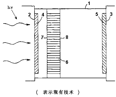
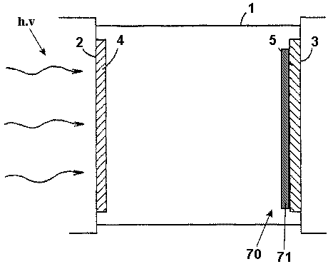
[0036] figure 1 An example of a vacuum tube such as an image intensifier is schematically shown in cross section. The image intensifier tube comprises a tubular housing 1 with an entrance or cathode window 2 and a detection or anode window 3 . The housing can be made of glass like the cathode and anode windows. The detection window 3 (detection window) is also often an optical fiber plate or is configured as a scintillation screen or a scintillation screen or a pixelated element array (such as a semiconductor active pixel array). The housing can also be made of metal if the cathode and possibly the anode are arranged in an insulated manner in the housing, eg by using separate charge carriers.

[0037] If the image intensifier is designed to receive X-rays, the cathode window can be made of thin metal. However, the anode window may be light transmissive. The cathode 4 can also be provided directly on the input face 7 of the channel plate 6 . All these variables are known p...


PUM

PropertyMeasurementUnit
Bandgapaaaaaaaaaa

Abstract

The invention relates to an electron multiplying structure for use in a vacuum tube using electron multiplying and to an vacuum tube using electron multiplying provided with such an electron multiplying structure. According to the invention an electron multiplying structure is proposed for use in a vacuum tube using electron multiplying, the electron multiplying structure comprising an input face intended to be oriented in a facing relationship with an entrance window of the vacuum tube, an output face intended to be oriented in a facing relationship with a detection surface of the vacuum tube, wherein the electron multiplying structure at least is composed of a semi-conductor material layer adjacent the detection windows.

Description

technical field [0001] The present invention relates to electron multiplying structures using electron multiplying vacuum tubes. [0002] The present invention also relates to a vacuum tube using electron multiplication having the electron multiplication structure. [0003] Note that vacuum tube structures used in this application for electron multiplication include - among others - image intensifier tube devices, open-face electron multipliers, channel multipliers, microchannel plates, and packaged devices like image intensifiers and merging elements or like Photomultiplier tubes, subassemblies of discrete multiplier electrodes, microchannel plates using secondary emission phenomena such as gain mechanisms. Such vacuum tubes are known in the art. They consist of a cathode which, under the influence of incident radiation such as visible light or X-rays, emits so-called photoelectrons which move towards the anode under the influence of an electric field. The electrons striki...

Claims


Application Information

Patent Timeline
IPC IPC(8): H01J31/50H01J40/06H01J1/32
CPCH01J31/506H01J43/16H01J1/32H01J43/04H01J31/48
Inventor 格特·努特则帕斯卡尔·拉乌特理查德·杰克曼
Owner 福托尼斯法国公司
Why Eureka
Try Eureka