External soil spraying machine and special two-stage energy-saving high-lift underflow pump for external soil spraying machine

A kind of soil spraying, high lift technology, applied in the direction of spreading seeders, fertilizers and seeding equipment, etc., can solve the problems of damage to the mud pump or diesel engine, reduce the lift and service life of the sprayer, complex structure, etc. Feeding auger, reducing failure prone points, optimizing the effect of the transmission mechanism

Active Publication Date: 2013-04-10
河南恒睿机械制造有限公司
View PDF5 Cites 9 Cited by
  • Summary
  • Abstract
  • Description
  • Claims
  • Application Information

AI Technical Summary

Problems solved by technology

[0003] At present, due to the different rotation direction of the impeller, the number of impellers, and the position of the inlet of the two-stage pump, the main pump of the existing guest soil sprayer has many disadvantages in the process of use, as follows: 1. The main pump of the sprayer Most of them are single-stage impellers, and the head is generally low; 2. The impeller of the main pump of the spray seeder is right-handed when viewed from the coupling end when it is working, which is the same as the rotation direction of the power machine such as a diesel engine, so it can only pass through the power machine. The coupling or the belt is connected at both ends on the same axis, that is, the installation position of the pump and the power machine (such as a diesel engine) can only be directly connected and installed at both ends of the pulley and the coupling, and cannot be installed in parallel. The overall length and floor area; and the rigid connection through the coupling will make the load too large due to the large particles entering the pump body and the impeller will be stuck, thereby damaging the mud pump or diesel engine; 3. Although the existing spraying machine adopts A two-stage pump is added, but due to the limitation of the impeller rotation direction and the position of the pump inlet, the feed auger and the reversing synchronous gearbox are added, and the structure is more complicated, which increases the failure maintenance points and power loss, and reduces the cost of pumping at the same time. The head and service life of the sprayer

Method used


Image

  • External soil spraying machine and special two-stage energy-saving high-lift underflow pump for external soil spraying machine
  • External soil spraying machine and special two-stage energy-saving high-lift underflow pump for external soil spraying machine
  • External soil spraying machine and special two-stage energy-saving high-lift underflow pump for external soil spraying machine

Examples


Embodiment 1

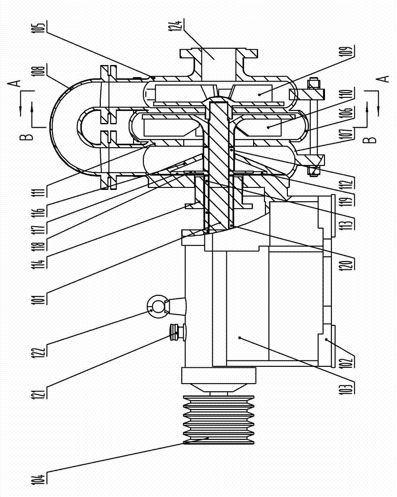
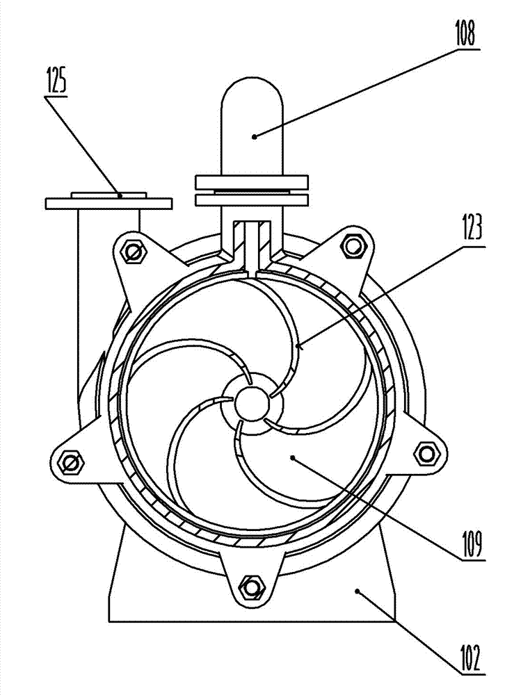
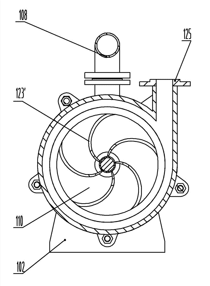
[0035] see Figure 1 to Figure 3 , in the figure, the double-stage energy-saving and high-lift special thick slurry pump 1 for soil seeding machine of the present invention includes a transmission shaft 101, a pump body is installed on the right side of the transmission shaft, and a bearing chamber 103 with a pump seat 102 is installed on the left side, A coupling 104 is installed at the left end, and the pump body includes a first-stage pump body 105, a second-stage pump body 106 and a second-stage feed pump body 107 that are sleeved on the transmission shaft in sequence from right to left. The pump body and the secondary feed pump body are connected by an elbow 108. The primary pump body is provided with a primary impeller 109. The primary impeller is fixedly sleeved on the right end of the transmission shaft, and the secondary pump body is provided with a secondary impeller 110. , a guard plate 111 is fixed between the secondary feeding pump body and the secondary pump body...

Embodiment 2

[0037] see Figure 4 to Figure 7 , in the figure, the double-stage energy-saving high-lift thick slurry pump special-purpose soil seeding machine of the present invention includes the above-mentioned double-stage energy-saving high-lift soil spraying machine special thick slurry pump 1, and also includes a frame 201, which is fixedly installed in the frame. The stirring tank 202 on one side has a stirring system installed inside the stirring tank, a feeding port 203 is arranged on the upper part of the outer side of the stirring tank, and the thick slurry pump is installed on the other side of the frame, which is respectively connected with the thick slurry pump and the stirring tank. The transmission mechanism connected to the system, and the power mechanism connected with the transmission mechanism, the lower part of the inner side of the mixing tank is provided with a water inlet pipe to connect with the thick slurry pump, and the top of the rack is provided with an operatin...


PUM


Abstract

The invention belongs to the technical field of spraying machinery, and particularly relates to an external soil spraying machine and a special two-stage energy-saving high-lift underflow pump for the external soil spraying machine. The underflow pump comprises a transmission shaft, a pump body, a bearing chamber and a coupling, wherein the pump body comprises a one-stage pump body, a two-stage pump body and a two-stage feed pump body; a one-stage impeller is fixedly mounted at the right end of the transmission shaft in a sleeving manner; an elbow is communicated between the one-stage pump body and the two-stage feed pump body; a guard plate is arranged between the two-stage feed pump body and the two-stage pump body; a locating sleeve is mounted on the transmission shaft between the two-stage feed pump body and the two-stage pump body in a sleeving manner; a two-stage impeller is mounted on the locating sleeve in a sleeving manner, and mounted between a radial flange at one end of the locating sleeve and the guard plate; a feed channel is formed between the guard plate and the locating sleeve; the one-stage impeller and the two-stage impeller are mounted back to back; the bending direction of a helical blade of the one-stage impeller is counterclockwise; the bending direction of a helical blade of the two-stage impeller is clockwise; a horizontal feed port is formed in the right end face of the one-stage pump body; and a discharge port is formed vertically in a tangential direction of the pump body on the front side of the two-stage pump body. The underflow pump is higher in lift, and is suitable for conveying viscous slurry; the structure of the spraying machine is simplified; the manufacturing cost and engineering use cost of the spraying machine are lowered; breakdown maintenance points of the spraying machine are decreased; and the power loss of equipment is reduced.

Description

technical field [0001] The invention belongs to the technical field of spraying machinery for planting herbs, shrubs, trees and other plants in slope greening, and in particular relates to a special two-stage thick slurry pump and a passenger soil spraying machine suitable for conveying viscous materials (mud, etc.). Soil sprayer. Background technique [0002] Nowadays, the guest soil spraying machine has gradually replaced the position of the dry spraying machine and the concrete delivery pump in the slope greening construction, and to a certain extent, it has solved the low efficiency of the dry spraying machine, high construction cost, more labor and the inconvenient movement of the delivery pump. , The disadvantage of construction danger. The so-called guest soil spraying machine is to mix grass seeds, shrubs, tree species, etc., with water-retaining agents, adhesives, plant fibers, planting soil and fertilizers, etc. The thick slurry pump sprays it on the slope. Sinc...

Claims


Application Information

Patent Timeline
Patent Type & Authority Applications(China)
IPC IPC(8): A01C7/08A01C7/06
Inventor 董世远
Owner 河南恒睿机械制造有限公司
Why Eureka
Try Eureka