Eureka AIR delivers breakthrough ideas for toughest innovation challenges, trusted by R&D personnel around the world.

Welding tool and method for electromagnetic plastic friction stir welding

A friction stir welding and friction stir technology, applied in non-electric welding equipment, welding equipment, manufacturing tools, etc., can solve problems such as hole defects, poor weldability, residual stress, etc., to achieve improved performance, low residual stress in welds, and workpiece deformation. small effect

Inactive Publication Date: 2013-04-10
HARBIN INST OF TECH
View PDF8 Cites 15 Cited by
  • Summary
  • Abstract
  • Description
  • Claims
  • Application Information

AI Technical Summary

Problems solved by technology

[0003] The purpose of the present invention is to solve the problems of residual stress, hole defects and poor weldability in existing friction stir welding joints, and provide an electromagnetic plastic friction stir welding welding tool and its method

Method used


Image

  • Welding tool and method for electromagnetic plastic friction stir welding
  • Welding tool and method for electromagnetic plastic friction stir welding
  • Welding tool and method for electromagnetic plastic friction stir welding

Examples


specific Embodiment approach 1

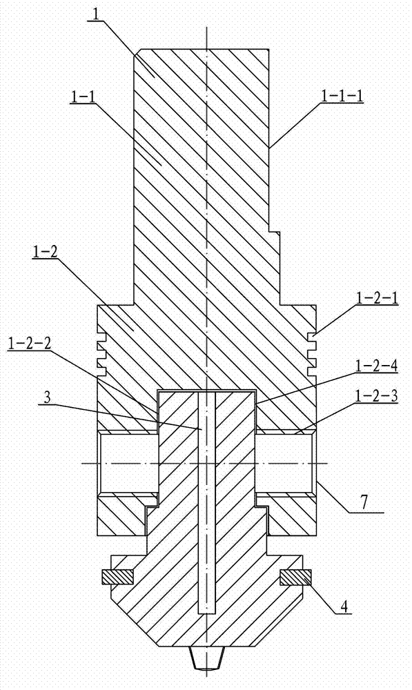
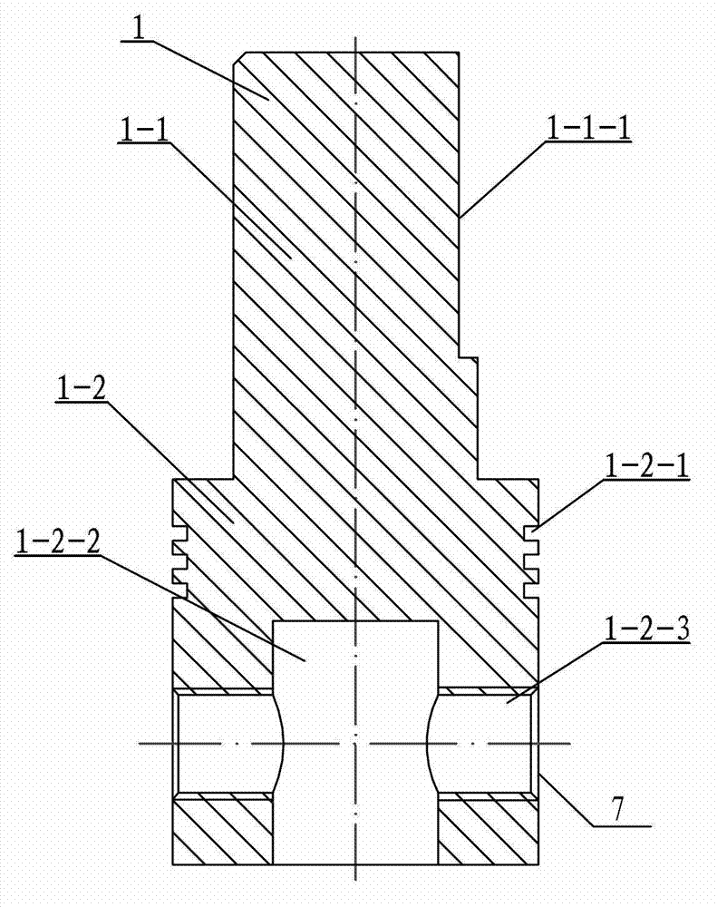
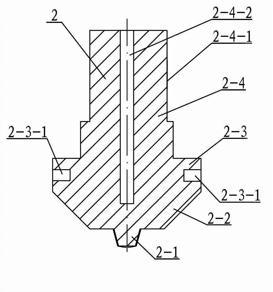
[0014] Specific implementation mode one: combine Figure 1 to Figure 4 Describe this embodiment, this embodiment comprises clamping body 1, stirring body 2, strong magnet 3 and 2~8 bar magnets 4, and described clamping body 1 is made up of upper cylinder 1-1 and lower cylinder 1- 2, the diameter of the upper cylinder 1-1 is smaller than the diameter of the lower cylinder 1-2, the upper and lower cylinders 1-1 and 1-2 are coaxially arranged and integrated, and the upper cylinder 1-2 The outer surface of 1 is provided with a welding tool clamping surface 1-1-1, and the outer surface of the lower cylinder 1-2 is provided with at least one annular heat insulation groove 1-2-1, and the lower cylinder 1-2 A clamping hole 1-2-2 is provided at the center of the lower end surface of the lower cylinder, and the side wall of the lower cylinder 1-2 corresponding to the clamping hole 1-2-2 is provided with a threaded passage perpendicular to the axis of the lower cylinder 1-2. Hole 1-2-3,...

specific Embodiment approach 2

[0015] Specific implementation mode two: combination figure 1 and image 3 The present embodiment will be described. The number of bar magnet slots 2 - 3 - 1 in this embodiment is the same as the number of bar magnets 4 . Other components and connections are the same as those in the first embodiment.

specific Embodiment approach 3

[0016] Specific implementation mode three: combination figure 1 and image 3 This embodiment will be described. The number of bar magnets 4 in this embodiment is four. Other steps are the same as in the second embodiment.


PUM

PropertyMeasurementUnit
electrical resistivityaaaaaaaaaa

Abstract

The invention discloses a welding tool and method for electromagnetic plastic friction stir welding, which relates to the welding tool and method for friction stir welding and solves the problems of residual stress, hole defect and poorer welding performance in an existing friction stir welding head. The welding tool is characterized in that 2-8 bar magnets are respectively arranged in 2-8 bar magnet grooves, and gaps are arranged between a connecting body and a clamping hole. The method comprises the following steps of 1, packaging insulation paper on the connecting body, arranging the connecting body in the clamping hole, arranging a strong magnet in a strong magnet groove, and arranging the bar magnets in the bar magnet grooves; 2, respectively adhering one conducting plate at the end surface positions at two ends of an abutting part of a to-be-welded workpiece, and respectively connecting an anode and a cathode of an additional power supply to the conducting plates which are arranged at the two ends; 3, enabling the current size to meet the requirement that the density of the current passing the workpiece to be larger than a critical value (106A / m<2>) of electroplasticity, and controlling the resistance thermal power of the workpiece to be under 100W; and 4, carrying out the electromagnetic plastic friction stir welding. The welding tool and the method, disclosed by the invention, are used for the friction stir welding of aluminum alloy, magnesium alloy, copper alloy and dissimilar materials.

Description

technical field [0001] The invention relates to a friction stir welding welding tool and method, in particular to an insulating welding tool for current-assisted friction stir welding and an electromagnetic plastic friction stir welding method realized by using the welding tool. Background technique [0002] As an advanced solid-phase joining technology, friction stir welding has been invented by The Welding Institute (TWI) in 1991. Due to its small welding deformation, small residual stress, good joint quality and fine-grained weld Forged organizational structure, without protective gas and filling materials, can eliminate welding defects such as pores, inclusions, cracks, and does not produce arc light, smoke, noise pollution, etc., and has the characteristics of simple welding operation, convenient automatic welding, high welding efficiency, etc. Welding has been widely used in many industrial manufacturing fields such as aerospace, aviation, shipbuilding, trains, automob...

Claims


Application Information

Patent Timeline
Patent Type & Authority Applications(China)
IPC IPC(8): B23K20/12B23K20/26
Inventor 黄永宪刘昊舒吕世雄万龙刘会杰冯吉才
Owner HARBIN INST OF TECH
Why Eureka
Eureka Blog
Learn More