
Tool setting method for micro CNC milling machine

A CNC milling machine, micro-miniature technology, applied in the direction of automatic control device, measuring/indicating equipment, feeding device, etc., can solve the problems of tool setting accuracy and low tool setting efficiency, achieve easy workpiece processing, simple principle, and improve tool setting The effect of precision

Active Publication Date: 2016-03-30
CHANGCHUN UNIV OF SCI & TECH
View PDF6 Cites 1 Cited by
  • Summary
  • Abstract
  • Description
  • Claims
  • Application Information

AI Technical Summary

Problems solved by technology

[0003] The purpose of the present invention is to propose a tool setting method for a miniature CNC milling machine to solve the problems of low tool setting accuracy and tool setting efficiency in the prior art

Method used


Image

  • Tool setting method for micro CNC milling machine
  • Tool setting method for micro CNC milling machine

Examples


Embodiment Construction

[0019] Embodiments of the present invention will be further described below in conjunction with the accompanying drawings.

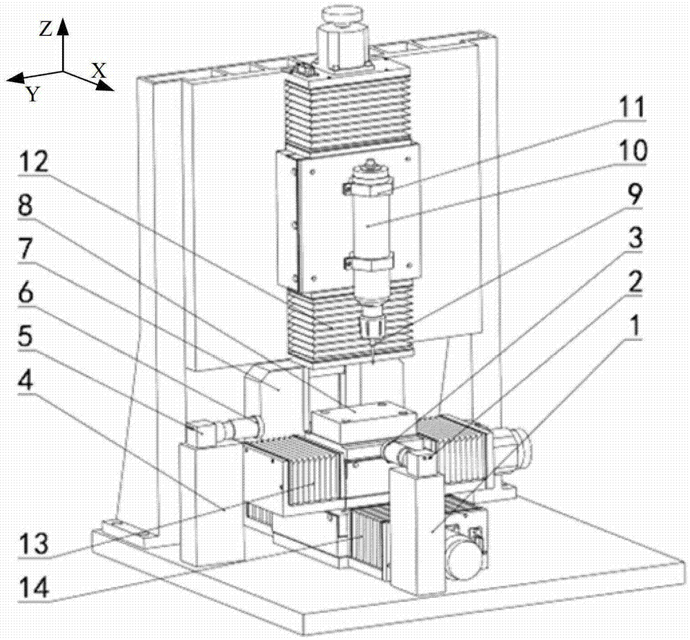
[0020] See attached figure 1 , the tool setting device for micro-sized CNC milling machine of the present invention comprises a CCD camera A2, a CCD camera B5 and a laser tool setting instrument 7 and a computer; the CCD camera A2 is placed orthogonally to the CCD camera B5, and the CCD camera A2 The image of the relative position of the workpiece 8 to be processed and the tool is collected in the X direction, and the CCD camera B5 collects the image of the relative position of the workpiece 8 to be processed and the tool along the Y direction. 14, the CCD camera A2, the CCD camera B5 and the laser tool setting instrument 7 are connected to the computer respectively, and the position of the cutter 11 is adjusted so that the tip of the tool 11 contacts the laser light emitted by the laser tool setting instrument 7. The computer realizes rapid tool settin...


PUM


Abstract

The invention provides a tool setting device and method of a mini-type numerical control milling machine, belongs to the field of a machine tool automatic control technology and aims to solve the problems in the prior art that the tool setting precision and the tool setting efficiency are low. The tool setting device comprises CCD (Charged Coupled Device) cameras, light sources and a laser tool setting instrument, wherein the two CCD cameras are orthogonally placed; the two light sources are respectively sleeved at the front ends of the two CCD cameras to illuminate a workpiece; after light is reflected, the light is received by the CCD cameras and is transmitted to an outer computer, so as to determine the positions of the workpiece and a tool in a machine tool coordinate system; the laser tool setting instrument and the workpiece are placed in parallel; a tool nose contacts laser emitted by the laser tool setting instrument and a signal generated by the laser tool setting instrument is transmitted to the outer computer, so as to further determine the position of the tool in the machine tool coordinate system; and data processing is carried out through computer program software so as to realize rapid tool setting. According to the tool setting device and method of the mini-type numerical control milling machine, the tool nose and the workpiece to be machined do not need to be actually contacted to carry out trial cutting, so that an error caused by contacting the tool nose with the workpiece to be machined is avoided, and the tool setting precision and the tool setting efficiency of the workpiece are improved.

Description

technical field [0001] The invention relates to a machine tool auxiliary device and a method thereof, in particular to a tool setting method for a miniature numerical control milling machine, which belongs to the technical field of machine tool automatic control. Background technique [0002] The tool setting device is an auxiliary device applied to CNC machine tools. During the processing of the workpiece, tool adjustment takes up a lot of time in the processing process, which is time-consuming and laborious, and it is not easy to be accurate. Finally, trial cutting is required. In addition, when processing small and complex parts, the accuracy of tool setting directly affects the machining accuracy of the workpiece surface. Therefore, the tool setting device is particularly important, which not only reduces the workload of tool setting personnel, but also improves the efficiency and accuracy of tool setting . The Chinese patent application with the application number 2010...

Claims


Application Information

Patent Timeline
Patent Type & Authority Patents(China)
IPC IPC(8): B23Q15/22B23Q17/22B23Q17/24
Inventor 许金凯于化东王晓冶于占江丁戗李一全张留新陈爽
Owner CHANGCHUN UNIV OF SCI & TECH
Learn More