Cable and manufacture method thereof
An optical cable and optical fiber technology, applied in the field of optical cable and its preparation, can solve the problems of poor hydrogen resistance performance of optical cable and increased optical fiber transmission loss, and achieve the effects of good tensile strength and compressive strength, and excellent comprehensive performance.
- Summary
- Abstract
- Description
- Claims
- Application Information
AI Technical Summary
Problems solved by technology
Method used
Image

Examples
preparation example Construction
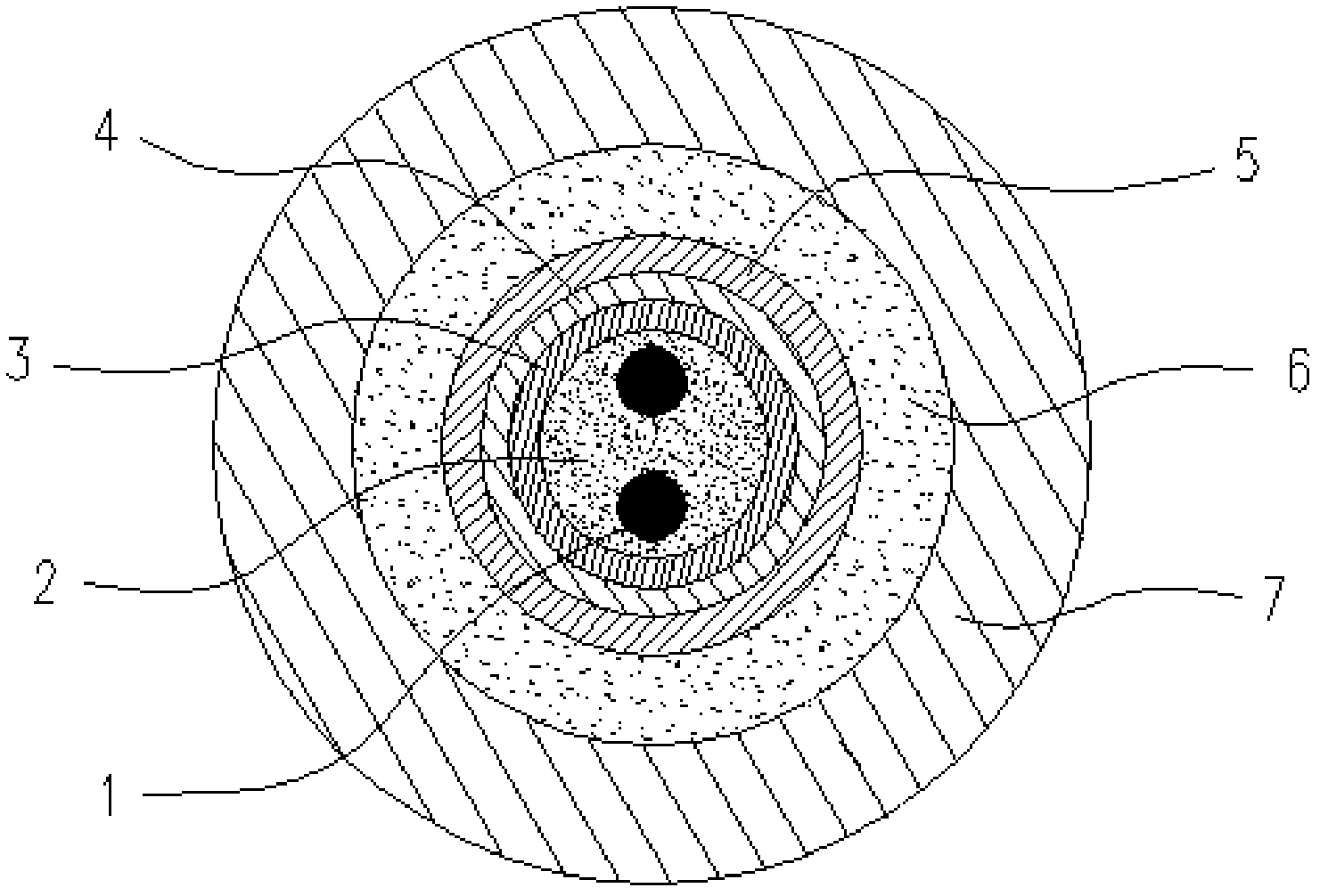
[0027] The method for preparing an optical cable provided by the present invention includes forming a fiber paste layer 2, a first protective layer 3, a hydrogen barrier layer 4, and a second protective layer 5 covering the surface of the optical fiber 1 from the inside to the outside.
[0028] The present invention does not specifically limit the method of forming the fiber paste layer 2 and the first protective layer 3. For example, a metal layer can be coated on the outside of the optical fiber 1, and filled between the optical fiber 1 and the metal layer. Hydrogen barrier fiber paste, thereby forming the fiber paste layer 2 and the first protective layer 3. It should be noted that the method of filling the hydrogen barrier fiber paste between the optical fiber 1 and the metal layer may be various existing filling methods, for example, the hydrogen barrier fiber paste may be applied while covering the metal layer. The filling between the optical fiber 1 and the metal layer may...
Embodiment 1
[0041] This embodiment is used to illustrate the preparation of the optical cable provided by the present invention.
[0042] The hydrogen barrier fiber paste used in this example was purchased from Unigel Company, and the model was OPGW-400H.
[0043] (1) Preparation of materials for forming colloidal hydrogen absorbing agent layer 6:
[0044] 30 kg of hydrogen barrier fiber paste and 17 kg of palladium sulfate ethanol solution (concentration of 85% by weight) were mixed to obtain the material for forming the colloidal hydrogen absorbing agent layer 6. Wherein, in the obtained material for forming the colloidal hydrogen absorbing agent layer 6, based on the total mass of the hydrogen barrier fiber paste, the content of the palladium sulfate is 48% by weight.
[0045] (2) Preparation of materials for forming the hydrogen barrier layer 4:
[0046] Stir and mix 5 kg of carbon, 10 kg of silicon carbide and 11 L of ethanol to obtain a colloidal mixture.
[0047] (3) Preparation of optical c...
Embodiment 2
[0050] This embodiment is used to illustrate the preparation of the optical cable provided by the present invention.
[0051] The hydrogen-blocking fiber paste used in this embodiment was purchased from Unigel Company, and the model was 128FN-WB.
[0052] (1) Preparation of materials for forming colloidal hydrogen absorbing agent layer 6:
[0053] 30 kg of hydrogen barrier fiber paste and 10.5 kg of an ethanol solution of tantalum carbonate (85% by weight) were mixed to obtain the material for forming the colloidal hydrogen absorbing agent layer 6. Wherein, in the obtained material for forming the colloidal hydrogen absorbing agent layer 6, the content of the tantalum carbonate is 30% by weight based on the total mass of the hydrogen barrier fiber paste.
[0054] (2) Preparation of materials for forming the hydrogen barrier layer 4:
[0055] Stir and mix 8 kg of carbon, 7 kg of magnesium oxide and 14 L of ethanol to obtain a colloidal mixture.
[0056] (3) Preparation of optical cable: ...
PUM
| Property | Measurement | Unit |
|---|---|---|
| Thickness | aaaaa | aaaaa |
| Thickness | aaaaa | aaaaa |
| Thickness | aaaaa | aaaaa |
Abstract
Description
Claims
Application Information
 - R&D
- Intellectual Property
- Life Sciences
- Materials
- Tech Scout
- Unparalleled Data Quality
- Higher Quality Content
- 60% Fewer Hallucinations
Browse by: Latest US Patents, China's latest patents, Technical Efficacy Thesaurus, Application Domain, Technology Topic, Popular Technical Reports.
© 2025 PatSnap. All rights reserved.Legal|Privacy policy|Modern Slavery Act Transparency Statement|Sitemap|About US| Contact US: help@patsnap.com