
Illumination driving device

A lighting driving and boosting module technology, applied in lighting devices, output power conversion devices, lamp circuit layout, etc., can solve problems such as device burnout, and achieve the effect of guaranteeing life.

Active Publication Date: 2013-04-10
BYD SEMICON CO LTD
View PDF3 Cites 11 Cited by
  • Summary
  • Abstract
  • Description
  • Claims
  • Application Information

AI Technical Summary

Problems solved by technology

[0004] In order to solve the problem that the lighting device in the existing lighting drive device flickers and causes the device to burn out

Method used


Image

  • Illumination driving device
  • Illumination driving device
  • Illumination driving device

Examples


Embodiment 1

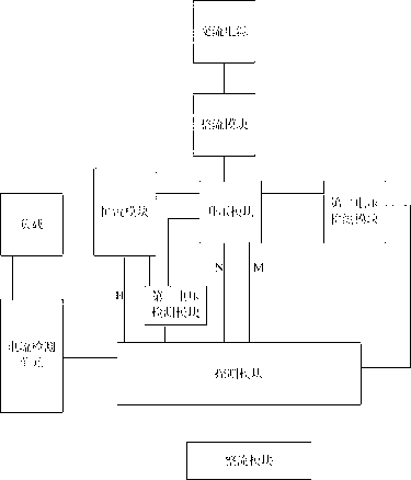
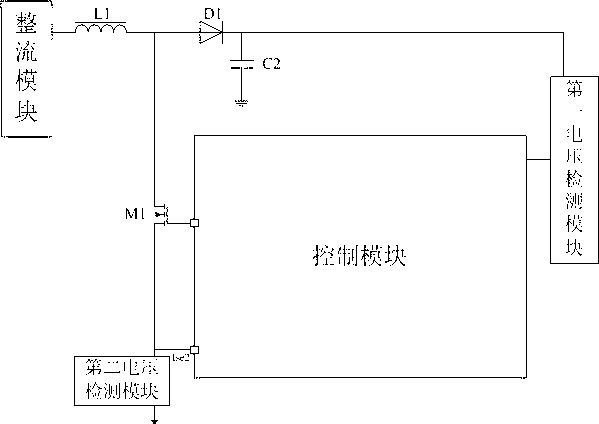
[0052] figure 2Shown is a module diagram of the lighting driving device of the present invention. As shown in the figure, the lighting driving device includes an AC power supply, a rectification module, a boost module, a constant current module, a first voltage detection module, a second voltage detection module, and a current detection module. unit, control module and load; the AC power supply is used to provide input current; the rectification module is used to convert the input current provided by the AC power supply into DC current and supply power to the control module; the boost module is used to increase the DC current of the rectification module and then Increase the output voltage; the constant current module outputs a constant current to the load according to the increased output voltage of the boost module; the first voltage detection module is connected between the boost module and the constant current module, and is used to detect the output of the boost module to...

Embodiment 2

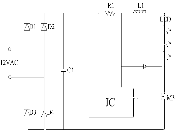
[0060] pass below Figure 9 Introduce the driving principle of the circuit. The AC power supply provides input current. The rectifier module composed of D3, D4, D5 and D6 converts the input current provided by the AC power supply into DC current. The first control unit turns on the first switch tube M1, and the input current is at Accumulated on the inductor L1 (the turn-on time of the first switch tube is related to the inductance of the inductor L1, if Va=Vsinwt, where Va represents the rectified input voltage, V represents the peak value of the rectified input voltage, and L1 represents the inductance of the inductor L1 amount, V1 represents the first preset value, R1 represents the second voltage detection module), the second voltage detection module composed of resistor R1 samples the current on the inductor L1, when the voltage on the resistor R1 reaches the second preset value , the first control unit turns off the first switching tube, the current on the first inductor...


PUM


Abstract

The invention relates to an illumination driving device. The illumination driving device comprises an alternating current power supply, a rectifier module, a voltage boosting module, a constant current module, a first voltage detecting module, a second voltage detecting module, an electric current detecting unit and a control module, wherein the alternating current power supply is used for providing input current, the rectifier module is used for converting the input current to direct current and supplying power for the control module, the voltage boosting module is used for increasing input voltage, the constant current module is used for outputting constant voltage to a load according to the input voltage, the first voltage detecting module detects voltage output to the constant current module, the second voltage detecting module detects voltage output by the voltage boosting module, the electric current detecting unit detects load current, and the control module is used for outputting a first control signal to drive the voltage boosting module when a detecting value of the first voltage detecting module is smaller than a first preset value, outputting a second control signal to switch off the voltage boosting module when a detecting value of the second voltage detecting module is larger than a second preset value, starting the constant current module and outputting a third control signal to switch off the constant current module when a voltage value detected by the electric current detecting unit is larger than a third preset value. The illumination driving device ceaselessly provides power for the load, so that the problem that the load is burnt out due to discontinuous current is prevented.

Description

technical field [0001] The invention relates to an illumination driving device. Background technique [0002] With the increasing awareness of environmental protection and energy saving, LEDs are constantly being used in various lighting occasions. As the cost of high-brightness LEDs continues to decrease and their performance continues to improve, it is expected that in the near future, the luminous efficacy of LEDs will be comparable to compact fluorescent lamps, and LEDs have the advantages of longer life and no mercury. Since LED lamps need to be driven by constant current, in order to meet higher conversion efficiency, a switching power supply constant current circuit is generally used to achieve constant current output. [0003] Such as figure 1 The typical electronic transformer LED driving scheme is shown. First, the 12VAC alternating current is generated by the electronic transformer. Four rectifier diodes D1~D4 convert the alternating current into a DC voltage an...

Claims


Application Information

Patent Timeline
Patent Type & Authority Applications(China)
IPC IPC(8): H05B37/02H02M7/162H02M1/36
Inventor 蒋幸福杨小华
Owner BYD SEMICON CO LTD
Features
  • Generate Ideas
  • Intellectual Property
  • Life Sciences
  • Materials
  • Tech Scout
  • Unparalleled Data Quality
  • Higher Quality Content
  • 60% Fewer Hallucinations
Learn More