Swivel Drive

A rotary drive and machine technology, applied in the direction of rotating bearings, anti-centrifugal force rotating parts, moving/orienting solar collectors, etc., can solve the problem of insufficient inspection and achieve the effect of reducing weight and stabilizing the connection

Inactive Publication Date: 2013-04-10
IMO HOLDING GMBH
View PDF6 Cites 10 Cited by
  • Summary
  • Abstract
  • Description
  • Claims
  • Application Information

AI Technical Summary

Problems solved by technology

Although recesses are provided at both the base and the cover through which the worm gear is accessible for mounting

Method used


Image

  • Swivel Drive
  • Swivel Drive
  • Swivel Drive

Examples


Embodiment Construction

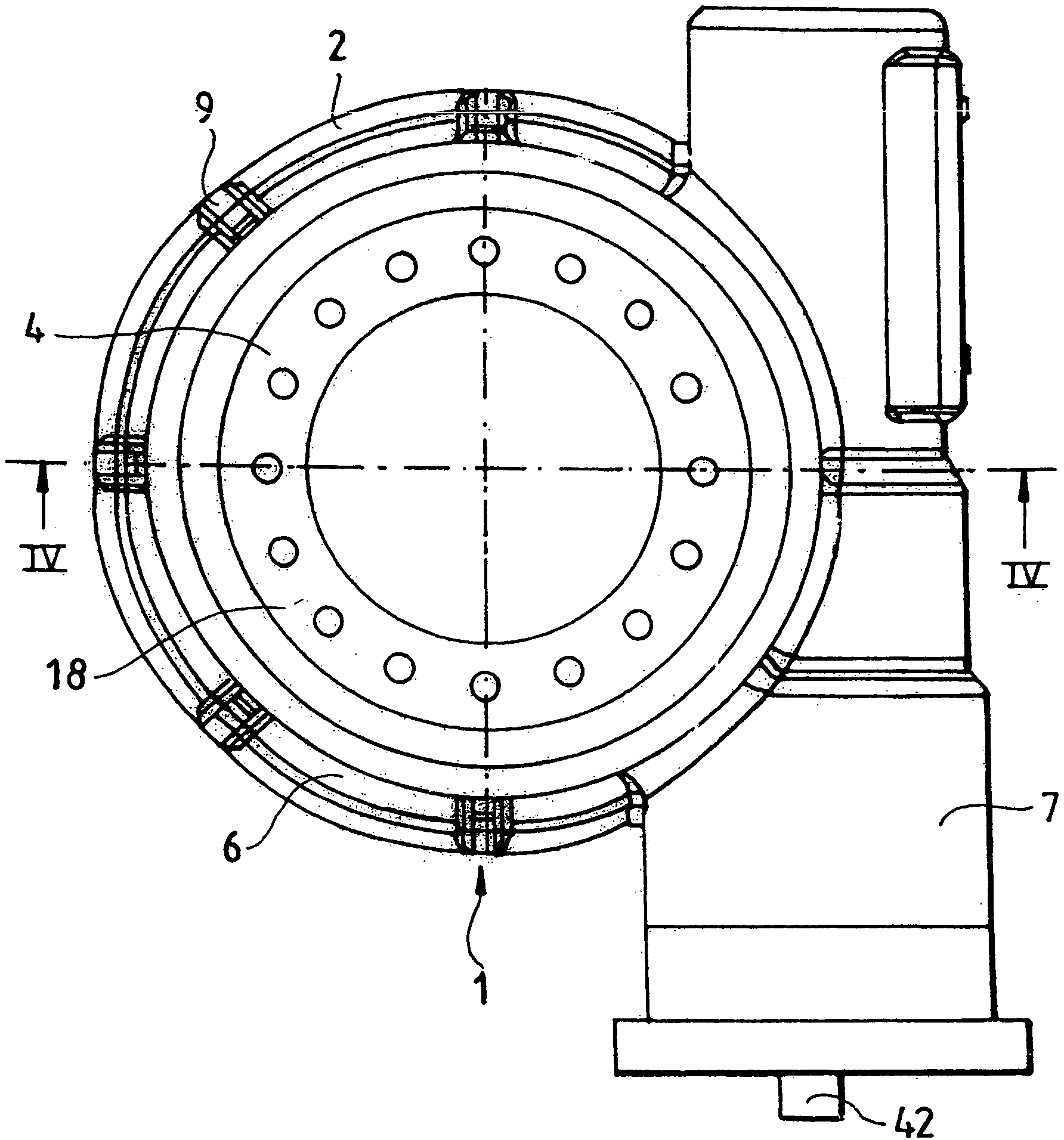
[0037] The device 1 according to the invention for driving one part of a machine or plant in rotation relative to another part of the plant or a base or chassis shows a particularly simple structure, namely a housing 2 in which a worm 3 and a turbine 4 are connected in Pivot in a rotatable way.

[0038] according to figure 1 The plan view of the housing 2 shows the two main parts of the housing 2, namely, the first annular housing part 6 which accommodates the turbine 4 concentric with the axis of revolution 5 of the rotary drive 1, and the housing part 6 for housing the worm The second straightly extending housing part 7 of 3.

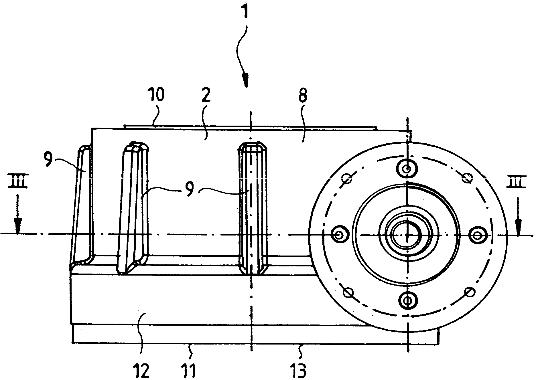
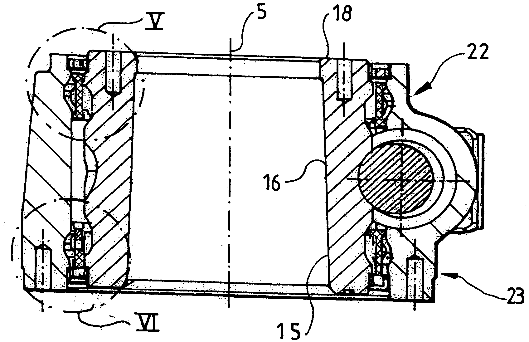
[0039] Figure 4 The cross-sectional view in FIG. 2 indicates the structure of the annular housing part 6 : said annular housing part 6 has a sleeve-like geometry substantially without a base or closure plate at its underside and without a cover at its upper side. As a distortion of the purely cylindrical geometry, some stiffening ribs 9 parallel t...


PUM


Abstract

The invention relates to a device (1) for the rotary drive of part of a machine or piece of equipment, for example a crane, an elevating working platform, a tracking photovoltaic assembly or heliostat or the like equipment for tracking mirrors within the context of a solar thermal power station, etc., on a foundation or on a chassis, for example of a heavy goods vehicle, or another part of a machine or piece of equipment, comprising a worm gear mechanism having a housing (2) which has a connecting surface for connecting to a part of the machine or piece of equipment, to a chassis or to a foundation, having a worm which can be caused to rotate manually or by means of a drive motor, and having a worm gear (4) which is rotatably mounted in the housing, in that, on both sides of the toothing of the worm gear provided to engage with the worm (3), at least one rolling contact bearing is provided in each case, and which has a connecting surface for connecting to a part of a machine or piece of equipment, to a chassis or to a foundation; according to the invention, the housing (2) and the worm gear (4) are each formed in one piece, wherein the smallest internal diameter of the housing (2) is larger than the largest external diameter of the worm gear (4).

Description

technical field [0001] The invention relates to a so-called rotary drive, which is a device for driving a part of a machine or plant in rotation on a base or chassis or relative to another part of the machine or plant, said base or chassis such as the base or chassis of a heavy vehicle, said machinery or equipment such as cranes, elevating tables, tracking photovoltaic components or heliostats or similar equipment for tracking reflectors in a solar thermal power station environment, etc., said Apparatus comprising a turbo mechanism having a housing having a connection surface for connection to a part of a machine or equipment, to a chassis or to a base, the turbo mechanism having a worm which can be rotated manually or by means of a drive motor and having a worm gear rotatably mounted in the housing, wherein at least one rolling contact bearing is provided on each side of both sides of the gear teeth of the worm gear arranged to mesh with the worm, and the worm gear includes m...

Claims


Application Information

Patent Timeline
IPC IPC(8): F16H1/16F16H57/039B66C23/84E02F9/12F24J2/54
CPCB66C23/84B66F11/04E02F9/123F05B2260/79F16C2300/14F16H57/039Y02E10/47F16C19/184F03D80/00F16C2350/26F16C2361/61F24S30/42F16H1/16Y10T74/1966Y02E10/72
Inventor 马丁·弗尔纳胡贝图斯·弗兰克乌韦·克林纳
Owner IMO HOLDING GMBH
Why Eureka
Try Eureka