An impact testing device

A technology of testing device and impact force, which is applied in the direction of impact test, measuring device, force/torque/power measuring instrument, etc., can solve the problems of low precision, high cost, and difficult realization, so as to prevent excessive instantaneous displacement and reduce Small amplitude and time, reducing the effect of pressure fluctuations

Inactive Publication Date: 2015-07-29
ZHEJIANG UNIV +1
View PDF12 Cites 0 Cited by
  • Summary
  • Abstract
  • Description
  • Claims
  • Application Information

AI Technical Summary

Problems solved by technology

[0003] 1. Terminal velocity method (although the impact energy measured by terminal velocity method is more accurate, it is more difficult to realize);
[0004] 2. The dynamometer method (the dynamometer method is very difficult to measure and calculate);
[0005] 3. Mechanical measurement method (the impact energy measured by the mechanical measurement method is not accurate enough and the precision is not high);
[0006] 4. Nitrogen chamber pressure measurement method (nitrogen chamber pressure measurement method cannot be used for impact machines without nitrogen chamber);
[0008] The test system of these methods is relatively complicated, and generally can only be carried out in the laboratory, the cost is high, and the implementation is very difficult

Method used


Image

  • An impact testing device
  • An impact testing device
  • An impact testing device

Examples


Embodiment 1

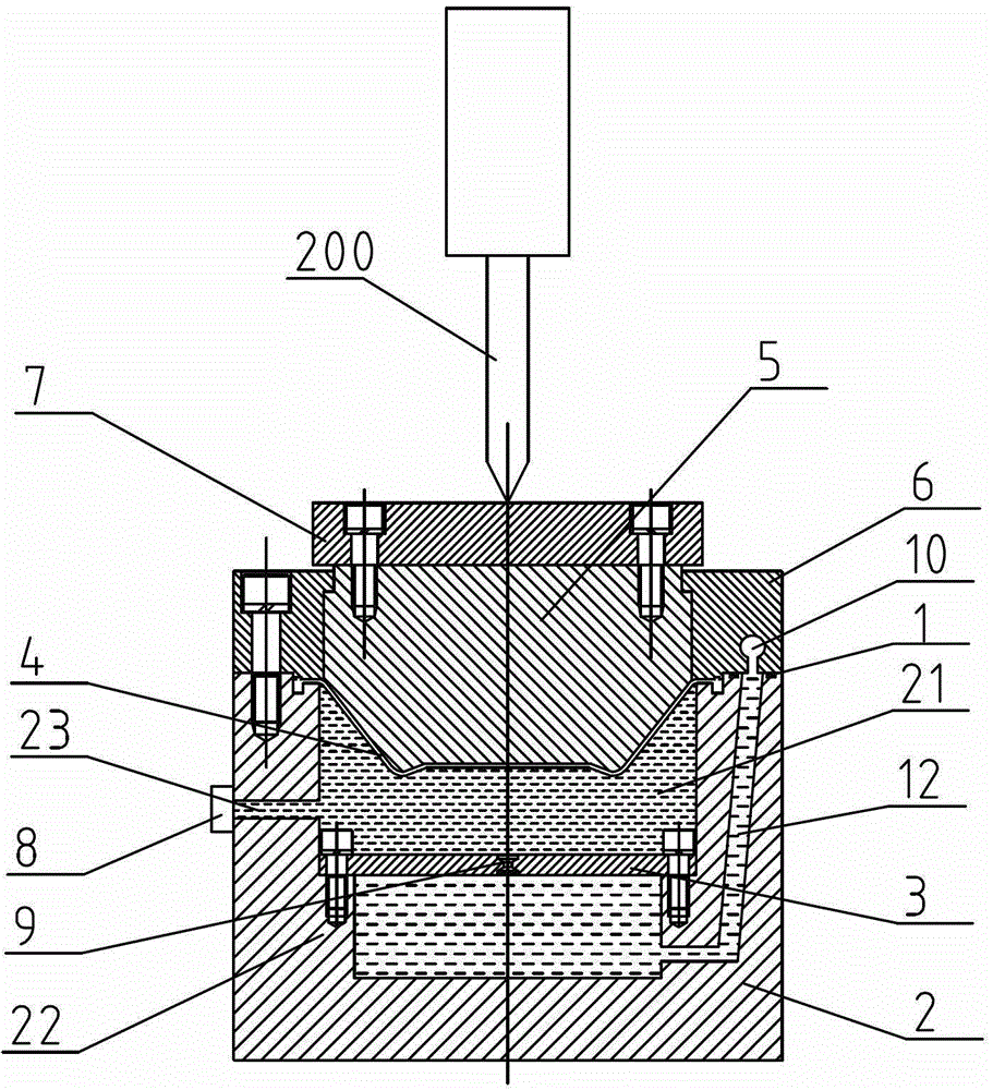
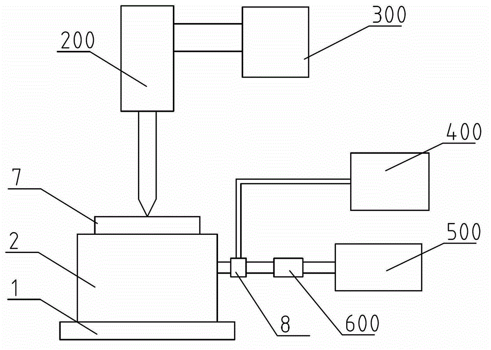
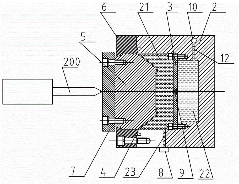
[0024] Embodiment 1, figure 1 A device for testing impact force is given, which includes a cylinder body 2, a cavity is provided in the cylinder body 2, and a damping orifice plate 3 fixed by bolts is arranged in the cavity, and the damping orifice plate 3 divides the cavity into two parts. Chamber I21 and chamber II22 (the upper chamber is chamber I21, and the lower chamber is chamber II22). The damping orifice 3 is provided with at least one damping hole 9, such as figure 1 or image 3 As shown, what is adopted in this embodiment is a damping hole 9 . The upper end of the chamber I21 is fixed with a rubber cup 4, and the chamber I21 and the chamber II22 are sealed through the rubber cup 4 (that is, the oil in the chamber I21 and the chamber II22 can be sealed through the rubber cup 4, so that the chamber I21 And the oil in the chamber II22 will not overflow). A piston 5 is arranged above the rubber cup 4; an upper cover 6 (that is, an annular upper cover 6) that matches ...

Embodiment 2

[0038] For some impact devices that strike in the horizontal direction, the present invention proposes Embodiment 2;

[0039] Embodiment 2, image 3 A kind of impact force testing device is provided, and the concrete structure except air bubble 10, oil channel 12 and sealing device 1 is exactly the same as embodiment 1; image 3 As shown, when the impact force is applied to the side of the device, the bubble 10 is still located at the top of an impact test device of the present invention, and the gas in the bubble 10 will not enter the oil. The specific implementation process of this embodiment is exactly the same as that of Embodiment 1.


PUM


Abstract

The invention discloses an impact force testing device, which comprises an external power supply and a displaying device, wherein the external power supply is connected with the displaying device; the impact force testing device is characterized by comprising a cylinder body (2), wherein a holding cavity with a bottom and without a top is arranged in the cylinder body (2), and a rubber leather bowl (4) is arranged on the upper end of the holding cavity; a piston (5) is arranged on the rubber leather bowl (4); an upper cover (6) is arranged on the upper end of the cylinder body (2); a damping hole plate (3) is arranged in the holding cavity, and the damping hole plate (3) is used for dividing the holding cavity into a holding cavity I (21) and a holding cavity II (22) from top to bottom; and a sensor (8) is arranged on the side wall of the cylinder body (2), and the sensor (8) is connected with the external power supply and in signal connection with the displaying device.

Description

technical field [0001] The invention relates to the field of impact performance testing, in particular to an impact testing device. Background technique [0002] Impact machinery is widely used in infrastructure or engineering construction, and the detection of impact energy is of great significance to the design, production and acceptance of impact machinery. The commonly used impact energy testing methods mainly include the following: [0003] 1. Terminal velocity method (although the impact energy measured by terminal velocity method is more accurate, it is more difficult to realize); [0004] 2. The dynamometer method (the dynamometer method is very difficult to measure and calculate); [0005] 3. Mechanical measurement method (the impact energy measured by the mechanical measurement method is not accurate enough and the precision is not high); [0006] 4. Nitrogen chamber pressure measurement method (nitrogen chamber pressure measurement method cannot be used for imp...

Claims


Application Information

Patent Timeline
Patent Type & Authority Patents(China)
IPC IPC(8): G01L5/00G01M7/08
Inventor 丁凡时新生赖伟强满在朋丁川刘硕黄挺峰
Owner ZHEJIANG UNIV
Why Eureka
Try Eureka