Building method for laser welding heat source model

A laser welding and heat source model technology, which is applied in special data processing applications, instruments, electrical digital data processing, etc., can solve the problems of difficult realization of laser heat source and low calculation efficiency

Active Publication Date: 2013-04-17
HARBIN INST OF TECH
View PDF2 Cites 24 Cited by
  • Summary
  • Abstract
  • Description
  • Claims
  • Application Information

AI Technical Summary

Problems solved by technology

[0004] The present invention aims to solve the problems of difficult realization of laser heat source and low calculation efficiency in

Method used


Image

  • Building method for laser welding heat source model
  • Building method for laser welding heat source model
  • Building method for laser welding heat source model

Examples


specific Embodiment approach 1

[0037] Specific embodiment one: the establishment method of a kind of laser welding heat source model of this embodiment is realized according to the following steps:

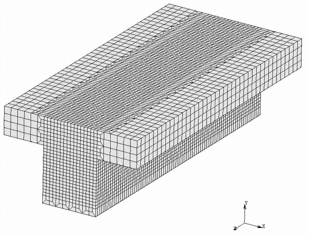
[0038] Step 1: Establish a 3D finite element mesh model:

[0039] Establish the geometric model of the workpiece in the 3D modeling software, and use meshing software or finite element calculation software to mesh the workpiece;

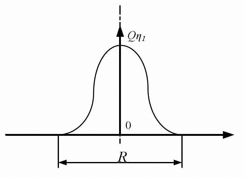
[0040] Step 2: Establish a Gaussian heat source model on the surface of the heat source:

[0041] q ( x , y , t ) = 3 Q η 1 π R 2 exp ( - 3 ( x ...


PUM


Abstract

The invention relates to a building method for a welding heat source model, in particular to a building method for a laser welding heat source model. The method solves the problem in laser welding simulation of large-scale complex construction members that laser heat source achieving difficulty is large, and calculating efficiency is low. The method includes: step 1, building a three-dimensional finite element grid model; step 2, building a Gaussian heat source mode of a heat source surface; step 3, expanding welding energy along the laser welding pool depth direction; and step 4, solving a governing equation based on finite element software and conducting heat-machine coupling calculation, namely building of the laser welding heat source model is finished. The building method is applied to the field of welding.

Description

technical field [0001] The invention relates to a method for establishing a welding heat source model. Background technique [0002] As a high-efficiency, high-quality, high-precision and small deformation welding method, laser welding has been widely used and continuously developed, and has been developed rapidly in the fields of machinery manufacturing, aerospace, automobile industry and microelectronics industry. Especially in the field of aerospace, laser welding has made pioneering contributions in the application of the aviation industry because of its advantages of being able to realize the connection of various types of materials and having advantages that other fusion welding industries cannot match. The welding structure using laser welding has good effects in reducing aircraft manufacturing costs, shortening production cycles, reducing weight, improving mechanical properties of components, improving carrying capacity, and enhancing stability. At present, laser we...

Claims


Application Information

Patent Timeline
IPC IPC(8): G06F17/50
Inventor 董志波郑文健宋奎晶张家铭郭军礼王帅丽魏艳红
Owner HARBIN INST OF TECH
Why Eureka
Try Eureka