Hydrogen generation device and fuel cell system
一种燃料电池系统、生成装置的技术,应用在燃料电池、燃料电池助剂、固体电解质燃料电池等方向,能够解决氢生成装置结构复杂等问题,达到抑制放热量、抑制温度上升的效果
- Summary
- Abstract
- Description
- Claims
- Application Information
AI Technical Summary
Problems solved by technology
Method used
Image

Examples
no. 1 approach
[0032] Hereinafter, a first embodiment of the hydrogen generator of the present invention will be described.
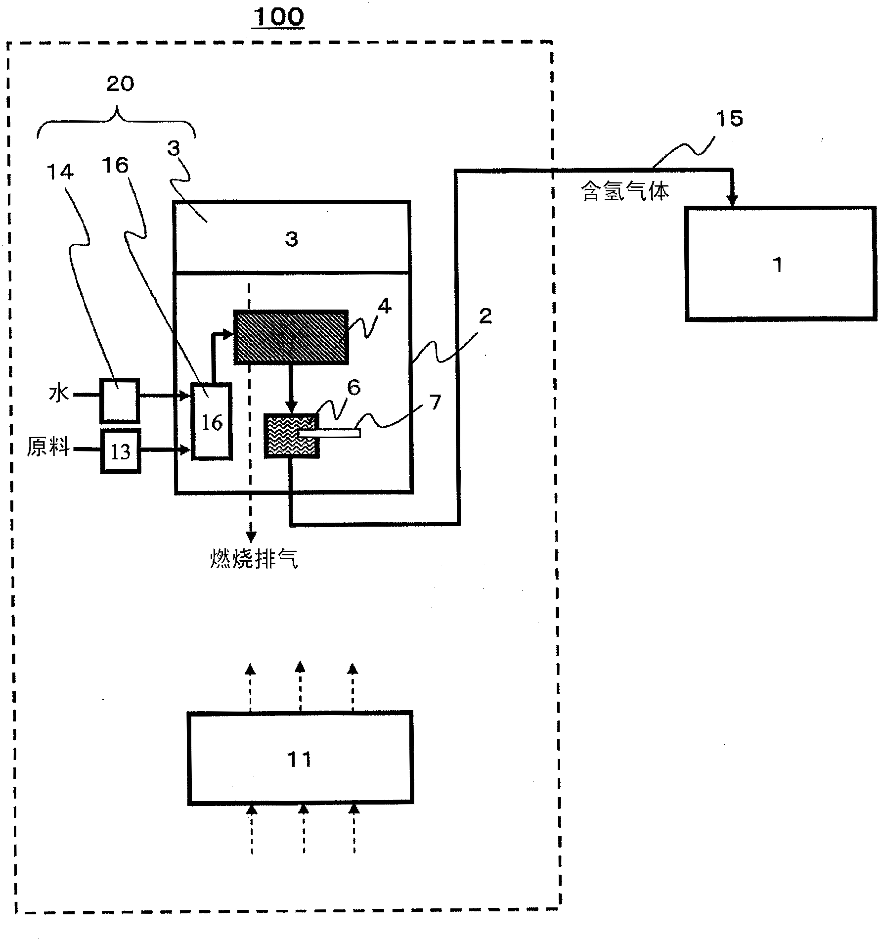
[0033] figure 1 It is a schematic diagram showing an example of a hydrogen generator according to an embodiment of the present invention.
[0034] The hydrogen generator 100 includes: a hydrogen generator 2 for generating a hydrogen-containing gas from a raw material; a raw material gas supplier 13 for supplying a raw material to the hydrogen generator 2; a steam supplier 20 for supplying water vapor to the hydrogen generator 2; A controller 11 that controls the operations of the gas supplier 13 and the steam supplier 20 .
[0035] In this embodiment, the water vapor supplier 20 is composed of the water supplier 14, the evaporator 16 that evaporates the water supplied from the water supplier 14 to generate water vapor, and the heater (in this example) that heats the evaporator 16. , is constituted by the burner 3). In addition, in this example, the heater which hea...
no. 2 approach
[0086] Next, a second embodiment of the fuel cell system of the present invention will be described. The fuel cell system of this embodiment includes: figure 1 On the other hand, the hydrogen generator 100 described above; a fuel cell as a hydrogen utilization device that utilizes the hydrogen generated in the hydrogen generator 100 .
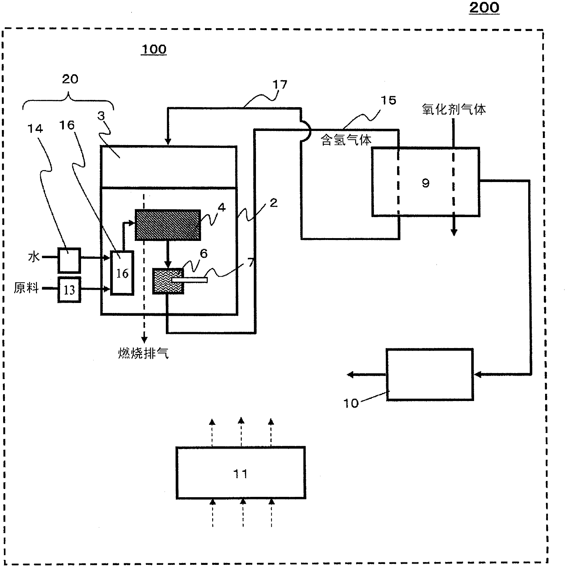
[0087] image 3 It is a schematic diagram showing an example of the fuel cell system of this embodiment. For simplification, for figure 1 The same structural elements are denoted by the same reference symbols, and explanations thereof are omitted.
[0088] The fuel cell system 200 includes: a hydrogen generator 100 ; a fuel cell 9 that generates electricity using hydrogen-containing gas generated by the hydrogen generator 100 ; and an inverter 10 . The hydrogen generator 100 includes: a hydrogen generator 2 ; a raw material gas supplier 13 that supplies raw materials to the hydrogen generator 2 ; a steam supplier 20 that supplies steam to t...
no. 3 approach
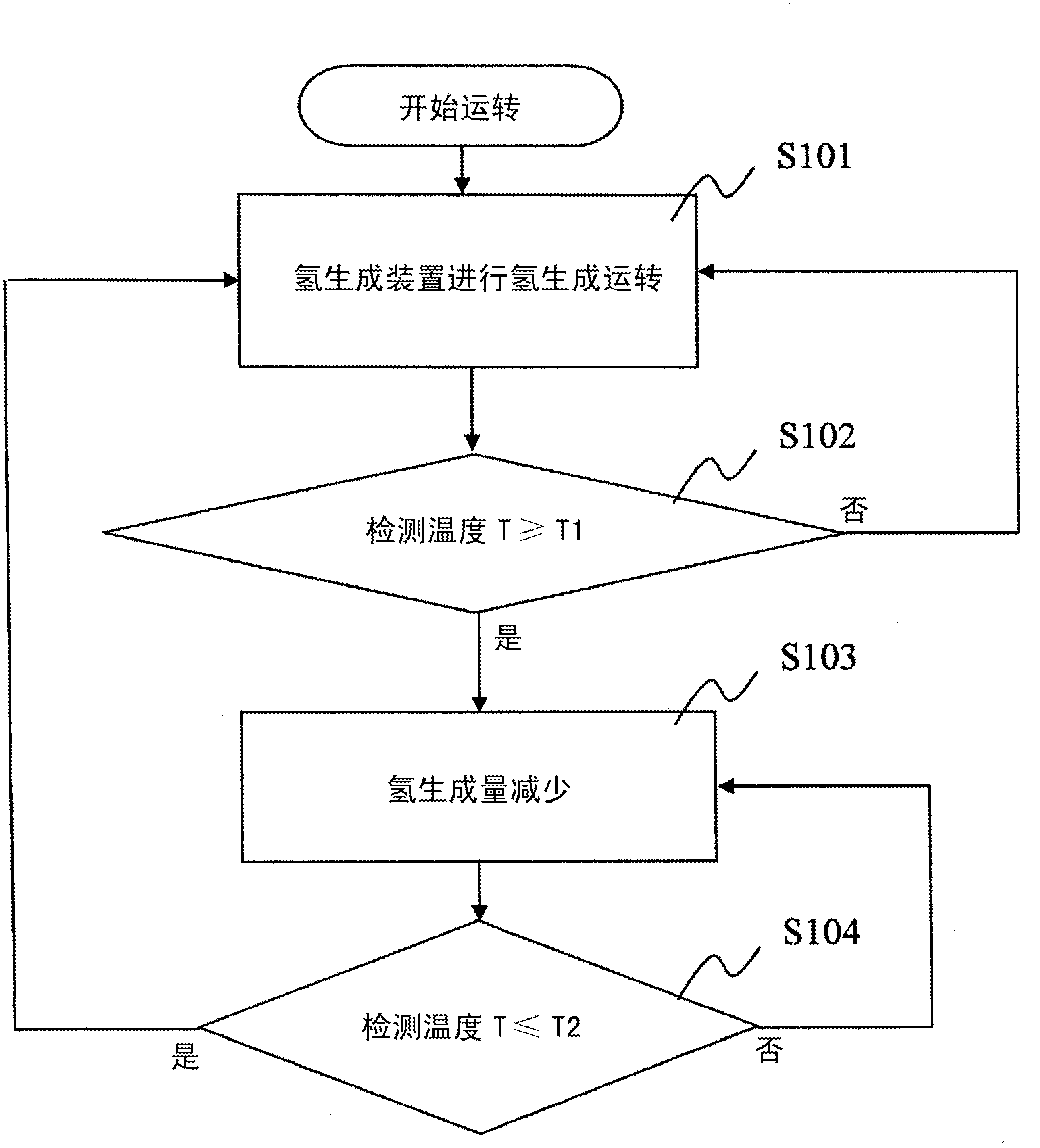
[0095] Hereinafter, a third embodiment of the fuel cell system of the present invention will be described. The fuel cell system of this embodiment is controlled so as to reduce the power generation output of the fuel cell system when the temperature rise of the methanator 6 is detected, and has a storage battery for storing electric power obtained by the fuel cell. refer to image 3 It is different from the fuel cell system 200 described above.
[0096] Figure 4 It is a schematic diagram showing an example of the fuel cell system of this embodiment. For simplicity, for image 3 The same structural elements are denoted by the same reference symbols, and explanations thereof are omitted.
[0097] In the fuel cell system 300 , the controller 11 is configured to control the inverter 10 and the battery 12 in addition to controlling the raw gas supplier 13 and the water vapor supplier 20 (here, the water supplier 14 ). By controlling the inverter 10, the target value of the po...
PUM
 Abstract
Description
Claims
Application Information
 - Generate Ideas
- Intellectual Property
- Life Sciences
- Materials
- Tech Scout
- Unparalleled Data Quality
- Higher Quality Content
- 60% Fewer Hallucinations
Browse by: Latest US Patents, China's latest patents, Technical Efficacy Thesaurus, Application Domain, Technology Topic, Popular Technical Reports.
© 2025 PatSnap. All rights reserved.Legal|Privacy policy|Modern Slavery Act Transparency Statement|Sitemap|About US| Contact US: help@patsnap.com