A continuous vacuum welding furnace and its welding method

A vacuum welding furnace and high vacuum technology, applied in welding equipment, electric heating devices, auxiliary devices, etc., can solve problems such as energy loss, lower welding efficiency, temperature stress fatigue damage of welding equipment, etc., to reduce energy loss and save welding time , The effect of short feeding and discharging routes

Active Publication Date: 2015-08-26
山东联盛电子设备有限公司
View PDF6 Cites 0 Cited by
  • Summary
  • Abstract
  • Description
  • Claims
  • Application Information

AI Technical Summary

Problems solved by technology

First of all, frequent heating and cooling will cause a large loss of energy; secondly, frequent heating and cooling will cause temperature stress fatigue damage to the welding equipment itself; moreover, heating and cooling will take a lot of time, reducing welding efficiency

Method used


Image

  • A continuous vacuum welding furnace and its welding method
  • A continuous vacuum welding furnace and its welding method
  • A continuous vacuum welding furnace and its welding method

Examples


Embodiment Construction

[0034] Below, the embodiments of the present invention will be further described in conjunction with the accompanying drawings.

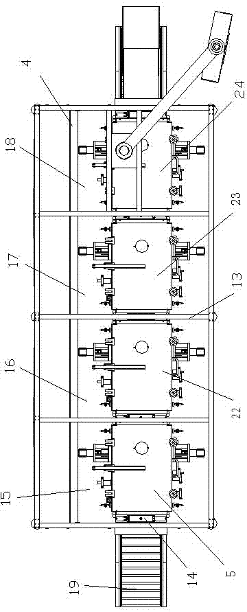
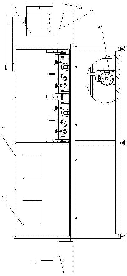
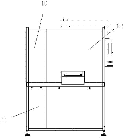
[0035] figure 1 , figure 2 , image 3 Show the structural schematic diagram of the main functional components of the continuous vacuum welding furnace. The present invention mainly consists of a feeding part 1, a frame 3, a heat insulating layer 4, a first vacuum chamber part 5, a second vacuum chamber part 22, a third vacuum chamber part 23, a fourth vacuum chamber part 24, Vacuum pump 6, programmable logic controller 7, discharge unit 8, electrical cabinet 10, pneumatic cabinet 11, working room 12 and so on. The working chamber 12 is a cuboid structure, and the first vacuum chamber part 5 , the second vacuum chamber part 22 , the third vacuum chamber part 23 and the fourth vacuum chamber part 24 are arranged in the working chamber sequentially from left to right. An electrical control device is provided in the electrical cabinet 10 , and a pn...


PUM


Abstract

The invention discloses a continuous vacuum welding furnace which comprises a working chamber, a feed inlet and a discharge outlet. Four vacuum cavity components are sequentially arranged inside the working chamber side by side and are respectively provided with independent temperature regulation and control systems, transmission systems, measurement systems and regulation and control systems; and a preheating area, a welding area, a precooling area and a cooling area which are four independent systems are formed inside the vacuum welding furnace, so that different processing procedures including a preheating stage, a heating stage, a precooling stage and a cooling stage can be respectively carried out. The invention further discloses an application method for the vacuum welding furnace. The continuous vacuum welding furnace and the application method have the advantages that the heating procedure and the cooling procedure can be carried out without interfering with each other under a vacuum or protective atmosphere condition, repeated temperature rise and temperature drop are omitted, accordingly, the welding time and power consumption can be saved, and the work efficiency and the welding quality can be improved.

Description

technical field [0001] The invention relates to a welding device and a welding method thereof, in particular to a continuous vacuum welding furnace and a welding method thereof. Background technique [0002] As electronic component packages shrink in size and power levels increase, the need for void-free soldering arises. Since welding in a low-oxygen or oxygen-free environment can reduce the generation of voids in the welding process and improve the quality of welding, people have always hoped that the welding process can be carried out in a low-oxygen or oxygen-free environment. However, most of the current welding furnaces are welded in the atmospheric environment, the generation of voids cannot be controlled, and the quality of welding is not high. [0003] In addition, for the vacuum welding furnace in the prior art, the whole process of welding is generally realized in one cavity space. Each soldering job needs to be heated from room temperature to soldering temperat...

Claims


Application Information

Patent Timeline
Patent Type & Authority Patents(China)
IPC IPC(8): B23K3/00B23K3/047B23K3/08B23K1/008
Inventor 马玉水
Owner 山东联盛电子设备有限公司
Why Eureka
Try Eureka