Cutting method of frangible super thin sheet or film material

A technology of thin film materials and cutting methods, which is applied in metal processing and other directions, can solve the problems of adsorption pipeline blockage, material damage, and the inability to ensure that all cut samples are fixed, and achieve the effect of avoiding damage

Inactive Publication Date: 2013-04-24
XINJIANG TECHN INST OF PHYSICS & CHEM CHINESE ACAD OF SCI
View PDF5 Cites 10 Cited by
  • Summary
  • Abstract
  • Description
  • Claims
  • Application Information

AI Technical Summary

Problems solved by technology

[0004] However, existing workpiece fixing methods all have defects
When using a clamp to hold a fragile ultra-thin sheet or film, the cut middle part cannot be fixed. If the ultra-thin sheet or film material is brittle, it is easy to crush the material during the clamping process, resulting in The damage of the material seriously affects the quality of the material. For example, when the ultra-thin ceramic material is clamped, the ceramic is easily crushed; when the ultra-thin sheet or film material is fixed on the worktable by the adhesive method, the cutting When separating

Method used


Image

  • Cutting method of frangible super thin sheet or film material
  • Cutting method of frangible super thin sheet or film material
  • Cutting method of frangible super thin sheet or film material

Examples


Embodiment 1

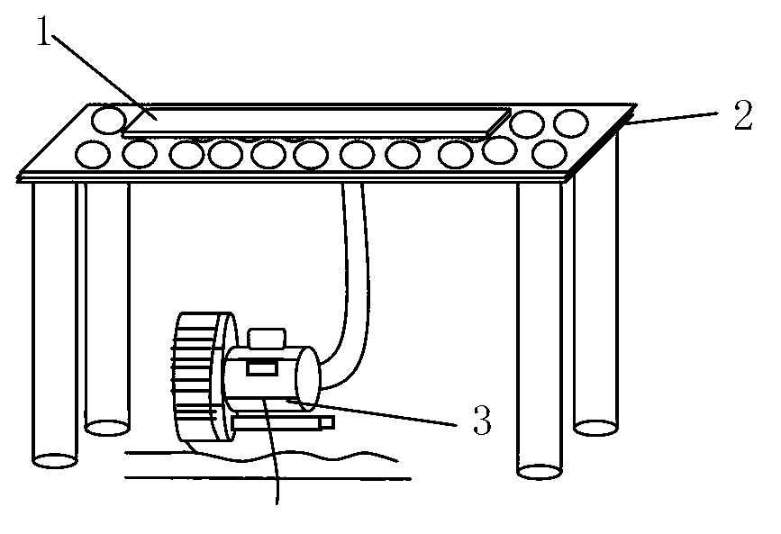
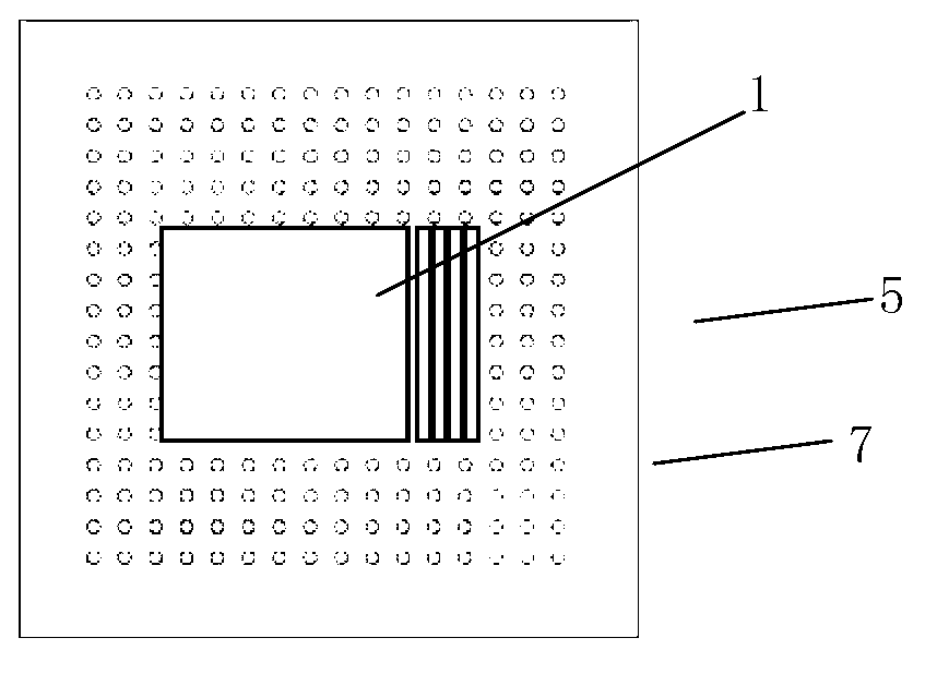
[0035] a. On the adsorption surface workbench 2 with adsorption holes 6, lay a breathable silicon wafer 5 with holes 7 of 0.5 μm, a spacing of 5 μm, and a thickness of 30 μm. The adsorption holes 6 on the adsorption surface workbench 2 and the vacuum pump 3 To connect, the fragile ultra-thin ceramic sheet 1 is placed on the gas-permeable silicon sheet 5;

[0036] b. Turn on the vacuum pump 3, through the hole 6 on the adsorption surface workbench 2 and the hole 7 on the air-permeable silicon wafer 5, the fragile ultra-thin ceramic sheet 1 is tightly adsorbed on the surface of the air-permeable silicon wafer 5, on the adsorption surface workbench 2 The negative pressure between the gas-permeable silicon wafer 5 is -50kpa, making the gas-permeable silicon wafer 5 a secondary adsorption table during work;

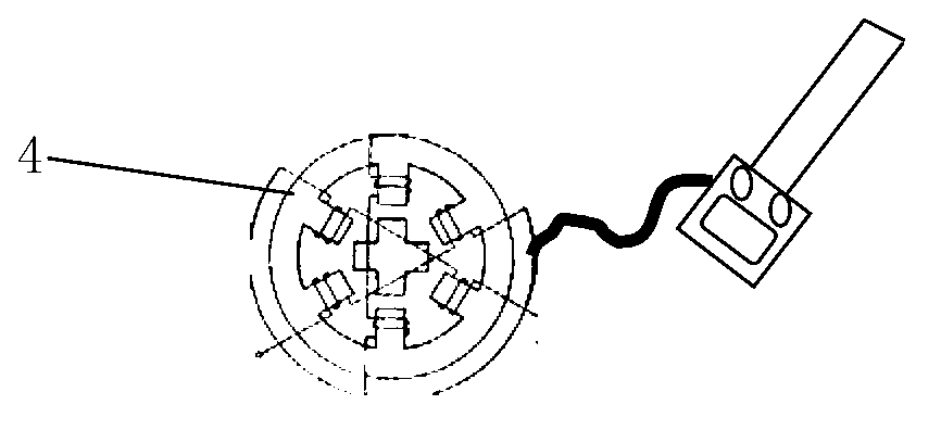
[0037] c. Connect the stepping motor 4 with a mechanical cutter, control the stepping motor 4 with a computer program, and use a mechanical cutter with a blade of 10nm to cut ...

Embodiment 2

[0041] a. On the adsorption surface workbench 2 with adsorption holes 6, lay a breathable silicon wafer 5 with holes 7 of 1.0 μm, a spacing of 8 μm, and a thickness of 50 μm. The adsorption holes 6 on the adsorption surface workbench 2 and the vacuum pump 3 To connect, the fragile ceramic film 1 is placed on the gas-permeable silicon wafer 5;

[0042]b. Turn on the vacuum pump 3, and through the holes 6 on the adsorption surface workbench 2 and the holes 7 on the air-permeable silicon wafer 5, the fragile ceramic film 1 is tightly adsorbed on the surface of the air-permeable silicon wafer 5. The negative pressure between the silicon wafers 5 is -40kpa, making the air-permeable silicon wafer 5 a secondary adsorption platform during work;

[0043] c. Connect the stepping motor 4 with a mechanical cutter, use a computer program to control the stepping motor 4, and use a mechanical cutter with a blade of 30 nm to cut the fragile ceramic film. After cutting once, follow the predete...

Embodiment 3

[0047] a. On the adsorption surface workbench 2 with adsorption holes 6, lay a breathable silicon wafer 5 with holes 7 of 5.0 μm, a spacing of 10 μm, and a thickness of 80 μm. The adsorption holes 6 on the adsorption surface workbench 2 and the vacuum pump 3 Connecting, placing the fragile ultra-thin chip 1 on the air-permeable silicon chip 5;

[0048] b, turn on the vacuum pump 3, through the hole 6 on the adsorption surface workbench 2 and the hole 7 on the air-permeable silicon wafer 5, the fragile ultra-thin chip 1 is tightly adsorbed on the surface of the air-permeable silicon wafer 5, between the adsorption surface workbench 2 and the air-permeable silicon wafer 5 The negative pressure between the breathable silicon wafers 5 is -30kpa, making the breathable silicon wafers 5 a secondary adsorption platform during work;

[0049] c. Connect the stepper motor 4 with a sharp metal wire, control the stepper motor 4 with a computer program, and cut the fragile ceramic chip with...


PUM

PropertyMeasurementUnit
Thicknessaaaaaaaaaa

Abstract

The invention relates to a cutting method of a frangible super thin sheet or a film material. A vacuum suction device utilized in the cutting method comprises a suction surface table, a stepper motor, a vacuum pump, silicon chips and cutting tools. By cutting tools such as mechanical knives, sharp metal silks, femtosecond laser or focused ion beams, the frangible super thin sheets or the film materials can be cut as required. The cutting tools are translated along the cutting section in the vertical direction by a predetermined distance, then cut the frangible super thin sheets or film materials as required, and repeat in this manner until the required numbers of samples are cut.

Description

Technical field: [0001] The invention relates to a cutting method of a fragile ultra-thin sheet or film material, which belongs to a method for non-destructively cutting the fragile ultra-thin sheet or film material into micron-sized samples. Background technique: [0002] Due to practical needs, it is often necessary to cut fragile ultra-thin sheets or thin film materials into micron-sized samples. But there are two problems in the process of cutting fragile ultra-thin sheets or thin film materials into micron-scale sizes. First of all, because there is at least one kind of interaction force when the cutting tool and the fragile ultra-thin sheet or film material are in contact with each other, it is easy to cause the fragile ultra-thin sheet or film material to be displaced during the cutting process, so that each time the cutting tool and the fragile Broken ultra-thin slices or thin films must be realigned before being applied to ensure the final size and number of sample...

Claims


Application Information

Patent Timeline
IPC IPC(8): B26D7/01
Inventor 蒋春萍孔雯雯高博常爱民
Owner XINJIANG TECHN INST OF PHYSICS & CHEM CHINESE ACAD OF SCI
Why Eureka
Try Eureka