
Gear carburization thermal treatment tool

A gear and carburizing technology, used in heat treatment furnaces, heat treatment equipment, manufacturing tools, etc., can solve the problems of large end face distortion, high manufacturing costs, and difficult management, and achieve low manufacturing difficulty, simple installation, and economical improvement. effect of benefit

Active Publication Date: 2013-04-24
HARBIN DONGAN AUTO ENGINE
View PDF4 Cites 7 Cited by
  • Summary
  • Abstract
  • Description
  • Claims
  • Application Information

AI Technical Summary

Problems solved by technology

Usually, the tooling used for carburizing, quenching and tempering treatment is to make a heat-resistant steel plane with a square hole in the middle of the tooling, place the main reduction gear on it, and use the large end face of the workpiece as a support. The disadvantages are: In the process of heating and carburizing, the large end face plays a supporting role, and the distortion of the large end face is out of tolerance, which increases the scrap rate, resulting in high manufacturing cost and difficult management

Method used


Image

  • Gear carburization thermal treatment tool
  • Gear carburization thermal treatment tool
  • Gear carburization thermal treatment tool

Examples


Embodiment Construction

[0015] Embodiments of the present invention will be further described in detail below in conjunction with the accompanying drawings.

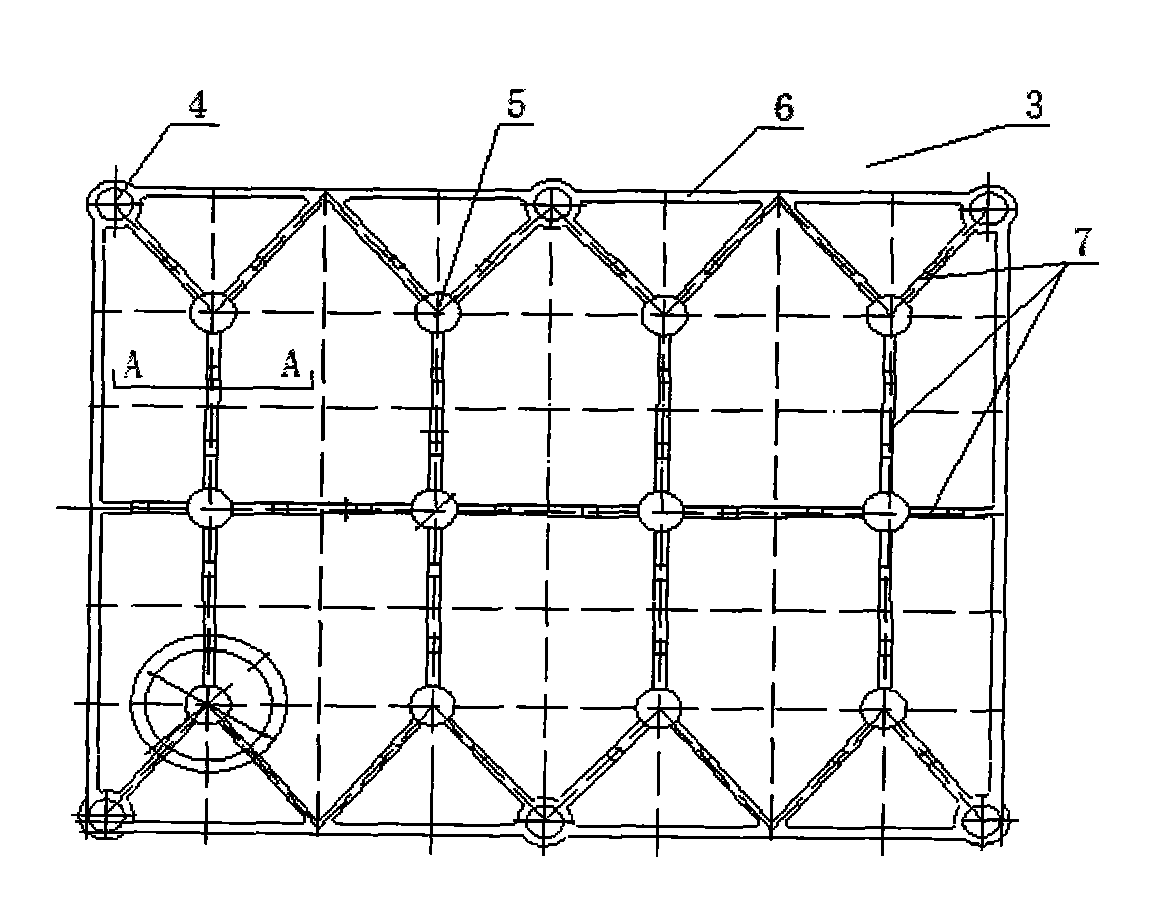
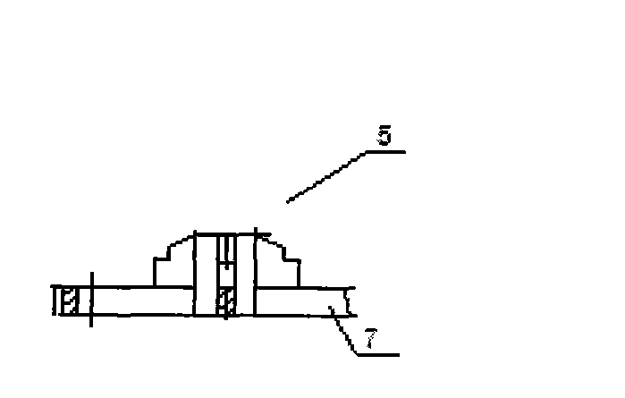
[0016] Depend on Figure 1-Figure 6 It can be seen that the present invention includes a gear support frame 3, the gear support frame 3 is surrounded by a support frame installation hole 4, and a plurality of support columns 5 are uniformly arranged in the middle, and the support columns 5 are connected by support ribs 7, and are close to The boundary of the gear support frame 3 is connected to the frame body frame 6 through the support ribs 7. The support column 5 is provided with a stepped table and the upper end is provided with chamfers. The cylindrical tooling angle mounting hole 9 corresponding to the mounting hole 4, a plurality of rectangular holes 10 are evenly opened on the chassis 1, and the lower end of the cylindrical tooling angle 2 is provided with a circular boss 8 near the end face, and the cylindrical tooling angle 2 The posi...


PUM


Abstract

The invention relates to a gear carburization thermal treatment tool which comprises gear support brackets, wherein support bracket installation holes are formed around the gear support brackets; a plurality of support columns are uniformly arranged at the middles of the gear support brackets; the support columns are connected together through support rib plates; the parts (of the support columns) close to the boundaries of the gear support bracket are connected with a bracket body frame through support rib plates; stair surfaces are formed on the support columns and chamfers are arranged at the upper ends of the support columns; a bottom disc takes the shape of a rectangle; cylindrical tool angle installation holes corresponding to the support bracket installation holes are formed at edges of the bottom disc; a plurality of rectangular holes are uniformly formed in the bottom disc; circular bosses are arranged at the lower end (close to the end surface) of the cylindrical tool angle; the parts (of cylindrical tool angles) below the bosses are inserted into the cylindrical tool angle installation holes; the parts (of the cylindrical tool angles) above the bosses are sequentially and serially connected with 1-7 layers of gear support brackets through the support bracket installation holes. The gear carburization thermal treatment tool is simple in structure, reasonable in design and low in manufacturing difficulty; the layers of the gear support brackets can be adjusted according to the number of gears to be treated, and the installation is simple and quick.

Description

technical field [0001] The invention relates to a heat treatment tool, in particular to a gear carburizing heat treatment tool used for the heat treatment of the main reduction gear of an automobile. Background technique [0002] At present, in the known processing of gear workpieces, the gear workpieces are processed to the final size of the tooth portion and the outer diameter of the gear workpiece to the final carburizing quenching and tempering treatment. After the gear workpiece is carburized, quenched and tempered in a multi-purpose furnace with controlled atmosphere, the tooth part of the workpiece and the large end face of the workpiece are not machined, but directly installed and used. Usually, the tooling used for carburizing, quenching and tempering treatment is to make a heat-resistant steel plane with a square hole in the middle of the tooling, place the main reduction gear on it, and use the large end face of the workpiece as a support. The disadvantages are: ...

Claims


Application Information

Patent Timeline
Patent Type & Authority Applications(China)
IPC IPC(8): C23F17/00C23C8/22C21D9/32
Inventor 张伟胡本洋黄道伟咸俊宝杨兵赵洪岩
Owner HARBIN DONGAN AUTO ENGINE
Learn More