Cycling switch valve under well

A circulating switch and valve body technology, which is applied in wellbore/well valve devices, wellbore/well components, earth-moving drilling, etc. The effect of blocking and increasing the service life

Active Publication Date: 2013-04-24
PETROCHINA CO LTD
View PDF9 Cites 10 Cited by
  • Summary
  • Abstract
  • Description
  • Claims
  • Application Information

AI Technical Summary

Problems solved by technology

Traditional high-pressure water injection wells generally adopt the method of venting and overflowing, and then start construction after reducing the pressure. This operation method has many problems such as long construction period, large volume of vented liquid, and environmental pollution. At the same time, it breaks the balance of injection-production well pattern , seriously affecting the effective development of the oilfield
In recent years, major oil fields have gradually promoted the application of snubbing technology to solve such problems. However, due to the lack of corresponding downhole tools in the pipe string structure of domestic water injection wells, plugging tools in the tubing must be used to seal the hole before tripping during snubbing operations. Plugging the tubing, and matching the completion tools to plug the tubing again during the drilling process, thus increasing the construction workload and increasing the operating cost
[0003] At present, there are also various types of valves used in high-pressure water injection wells, but these valves cannot fully realize the four functions of drilling under pressure, normal water injection, backwashing operations, and tripping under pressure. There are defects in the pressurized operation technology of water wells, which is not suitable for large-scale promotion and application

Method used


Image

  • Cycling switch valve under well
  • Cycling switch valve under well

Examples


Embodiment

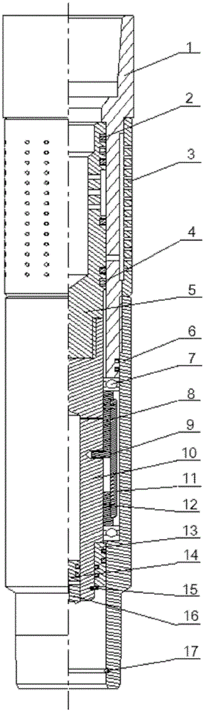
[0015] refer to figure 1 with 2 Embodiments of the present invention are further described:

[0016] The track cylinder 8 with track groove is set on the outside of the valve body 10 with threaded holes, and the sliding nail 9 passes through the track groove of the track cylinder 8 and is connected to the threaded hole on the valve body 10; the upper and lower ends of the track cylinder 8 are provided with rolling bearings 7. The sealing sleeve 13 with a sealing ring is set on the bottom of the valve body 10, and is fixed by the limit pin 15; on the upper part of the inner cavity of the valve body 10, there is an oil hole connecting the outer ring cavity of the valve body 10. The bottom end of the cavity is provided with a sliding plug 14 and a hollow plug 16; the protective tube 11 is fixed on the outside of the track tube 8; the lower joint 6 with an embedded circlip 17 at the bottom is set on the outside of the protective tube 11 and the sealing sleeve 13; The upper part...


PUM


Abstract

The invention discloses a cycling switch valve under a well. The cycling switch valve under the well is designed to satisfy various technological requirements of high-pressure water injection well working under pressure. A cycling locking mechanism is designed inside a valve to enable the cycling locking mechanism to smoothly achieve unlimited times of cycling opening and closing movements of the valve through pressure inside an oil pipe on the ground. Opening and closing of the valve are only controlled by pressure difference between oil and a sleeve pipe and oil pipe flow rate, and have nothing to do with formation pressure, and therefore the cycling switch valve under the well can bear larger formation pressure, and then reliable sealing and plugging of the oil pipe are achieved. Due to the fact that a self-sufficient type lubrication system is arranged in the valve, lubricating oil can be supplied timely, so that a reversing part of the cycling switch valve under the well is enabled to work in a good environment, and service life is prolonged. Reversing pressure difference and flow rate of the cycling switch valve under the well can be set through the change of the dimensional coordination of parts inside the cycling switch valve under the well, and therefore the cycling switch valve under the well is enabled to be applied to field operation within areas with different formation pressure.

Description

technical field [0001] The invention relates to a downhole circulation switch valve, which belongs to the technical field of oil and gas well engineering. Background technique [0002] Water injection is the basis for economical and effective development of oilfields, and is an effective means to enhance oil recovery and secondary oil recovery. In order to ensure the effect of water injection, it is necessary to carry out measures such as string inspection or workover operations. Traditional high-pressure water injection wells generally adopt the method of venting and overflowing, and then start construction after reducing the pressure. This operation method has many problems such as long construction period, large volume of vented liquid, and environmental pollution. At the same time, it breaks the balance of injection-production well pattern , seriously affecting the effective development of the oil field. In recent years, major oil fields have gradually promoted the app...

Claims


Application Information

Patent Timeline
Patent Type & Authority Applications(China)
IPC IPC(8): E21B34/08
Inventor 刘江波慕立俊刘明白小佩姜勇赵敏琦周学军
Owner PETROCHINA CO LTD
Why Eureka
Try Eureka