
Shield tunnel construction environment simulation unit

A construction environment and simulation device technology, applied in tunnels, teaching models, instruments, etc., can solve problems such as fixed excavation routes, small model soil box capacity, and narrow application area, and achieve rich stratum environment, eliminate boundary effects, and material capacity big effect

Inactive Publication Date: 2013-04-24
SOUTHWEST JIAOTONG UNIV
View PDF5 Cites 17 Cited by
  • Summary
  • Abstract
  • Description
  • Claims
  • Application Information

AI Technical Summary

Problems solved by technology

The construction environment of shield tunneling is complex and changeable, and often encounters weak, water-rich, broken and other stratum environments. The existing simulation system mainly uses similar materials in the model soil box to conduct a scale-down simulation test of the stratum environment. The model soil box The capacity is small, and different stratum environments can only be simulated by replacing similar materials. The stratum environment that can be simulated is simple; complex stratum environments such as bias voltage and high stress field cannot be simulated; at the same time, the shield section that can be simulated by the small-capacity model soil box The form is single, the tunneling route is fixed, and the applicable surface is narrow; it can only be used for the simulation of the shield tunneling process, ignoring the simulation of the shield tail segment assembly, shield tail ring removal, grouting and other processes, and does not simulate the tunneling in a complete sense The whole process
Of course, it is even more impossible to simulate the construction process of the shield tunnel under the complex three-dimensional space stress form and the auxiliary construction method for the construction

Method used


Image

  • Shield tunnel construction environment simulation unit

Examples


Embodiment

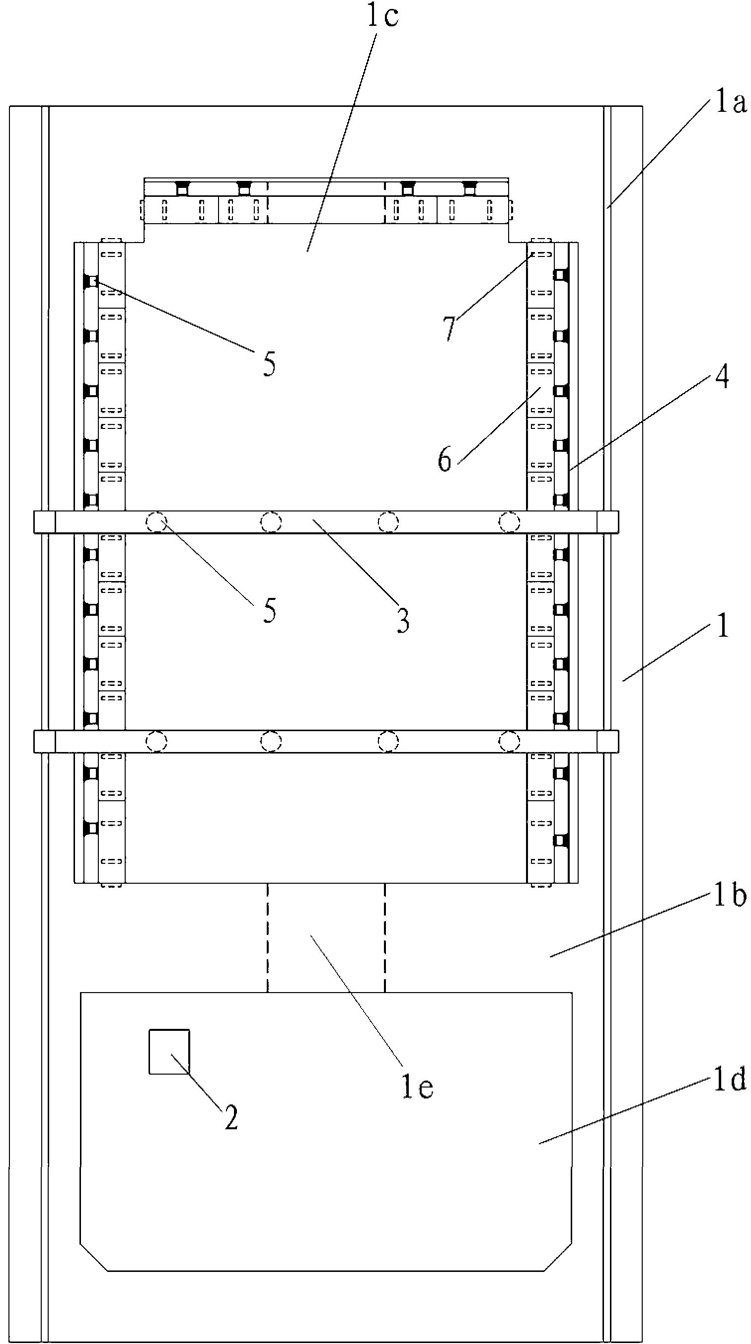
[0024] figure 1 It is shown that a shield tunnel construction environment simulation device includes a foundation groove 1, a hydraulic loading device 2, and a control device. It is characterized in that: the foundation groove 1 is a cuboid-shaped sunken reinforced concrete foundation groove. The tops of the left and right side walls of the tank 1 are provided with channels 1a, the casters of the columns on both sides of the mobile reaction frame 3 are installed in the channel 1a, and the lower surface of the mobile reaction frame 3 is provided with a plurality of jacks 5.

[0025] The foundation trench 1 is divided into an environmental simulation field 1c and a starting well 1d by a partition wall 1b along the longitudinal direction. The partition wall 1b is provided with a shield tunnel entrance 1e, and the left, right and front walls of the environmental simulation field 1c are A fixed anti-force grid 4 is installed, and a plurality of jacks 5 in the horizontal direction a...


PUM


Abstract

Disclosed is a shield tunnel construction environment simulation unit. A foundation trench of the shield tunnel construction environment simulation unit is a rectangular reinforce concrete foundation trench. The tops of the left and right walls of the foundation trench are provided with channels. Columns on two sides of a moving reaction frame are disposed in the channels. A plurality of jacks are disposed below the moving reaction frame. The foundation trench is longitudinally divided into an environment simulation site and a starting well by a partition wall. The partition wall is provided with a shield entry. Fixed reaction grids are disposed on the left wall, right wall and front wall of the environment simulation site respectively. A plurality of horizontal jacks are disposed on the fixed reaction grids. A sliding retainer wall unit is arranged in front of the jacks and is disposed at the bottom of the environment simulation site through slides. The jacks on the fixed reaction grids and the jacks on the moving reaction frame are both connected with a hydraulic loading device. The shield tunnel construction environment simulation unit is in an open large-space structure, capable of simulating rich stratum environments, available for large-scale similar model experiments, capable of effectively eliminating boundary effect, capable of more truly reflecting the complex shield tunnel construction environment, and is highly reliable.

Description

technical field [0001] The invention relates to a shield tunnel construction environment simulation device. Background technique [0002] Using the shield tunnel construction environment simulation device to conduct the shield tunneling model test is an important method to analyze the interaction between the complex stratum environment and the shield tunnel construction, the mechanical behavior of the tunnel lining structure, and the occurrence and development of shield tunnel diseases. [0003] Shield tunneling is a method of building tunnels by advancing in the stratum to prevent soil and sand from collapsing while excavating and lining the interior. The construction method of shield tunnel is usually suitable for weak stratum, and its interaction with the surrounding stratum environment is very large. During the construction, various auxiliary construction measures shall be supplemented according to the engineering hydrogeological characteristics of the traversing stratu...

Claims


Application Information

Patent Timeline
IPC IPC(8): E21D9/06G09B25/02
Inventor 何川张景晏启祥李铮耿萍
Owner SOUTHWEST JIAOTONG UNIV
Learn More