Exhaust system for combustion engine, combustion engine and transportion means

An exhaust system, internal combustion engine technology, applied in gas passages, exhaust devices, machines/engines, etc., can solve problems such as improving exhaust gas resistance and fuel consumption

Inactive Publication Date: 2013-04-24
GM GLOBAL TECH OPERATIONS LLC
View PDF4 Cites 6 Cited by
  • Summary
  • Abstract
  • Description
  • Claims
  • Application Information

AI Technical Summary

Problems solved by technology

However, it is also possible to increase exhaust gas resistance and fuel consumption due to the compact design

Method used


Image

  • Exhaust system for combustion engine, combustion engine and transportion means
  • Exhaust system for combustion engine, combustion engine and transportion means
  • Exhaust system for combustion engine, combustion engine and transportion means

Examples


Embodiment Construction

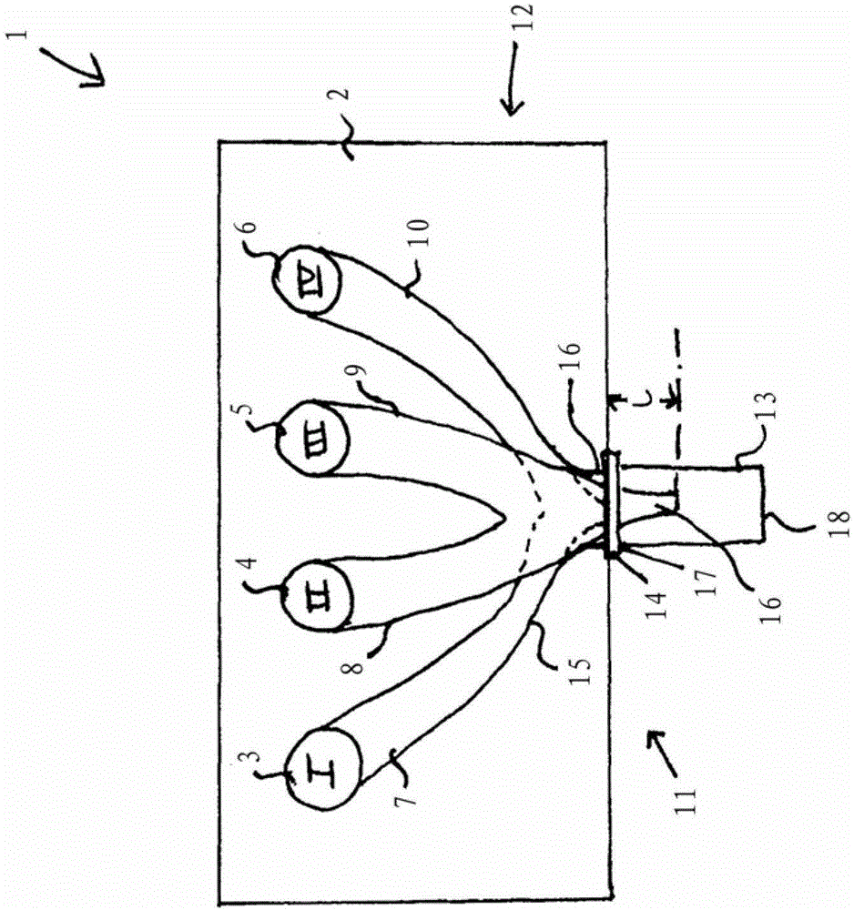
[0037] figure 1 A schematic plan view of the internal combustion engine 1 according to the first exemplary embodiment is shown. The internal combustion engine 1 has a cylinder head 2, in figure 1 Not shown in the engine block and the 4 cylinders 3, 4, 5, 6, which form the combustion chambers.

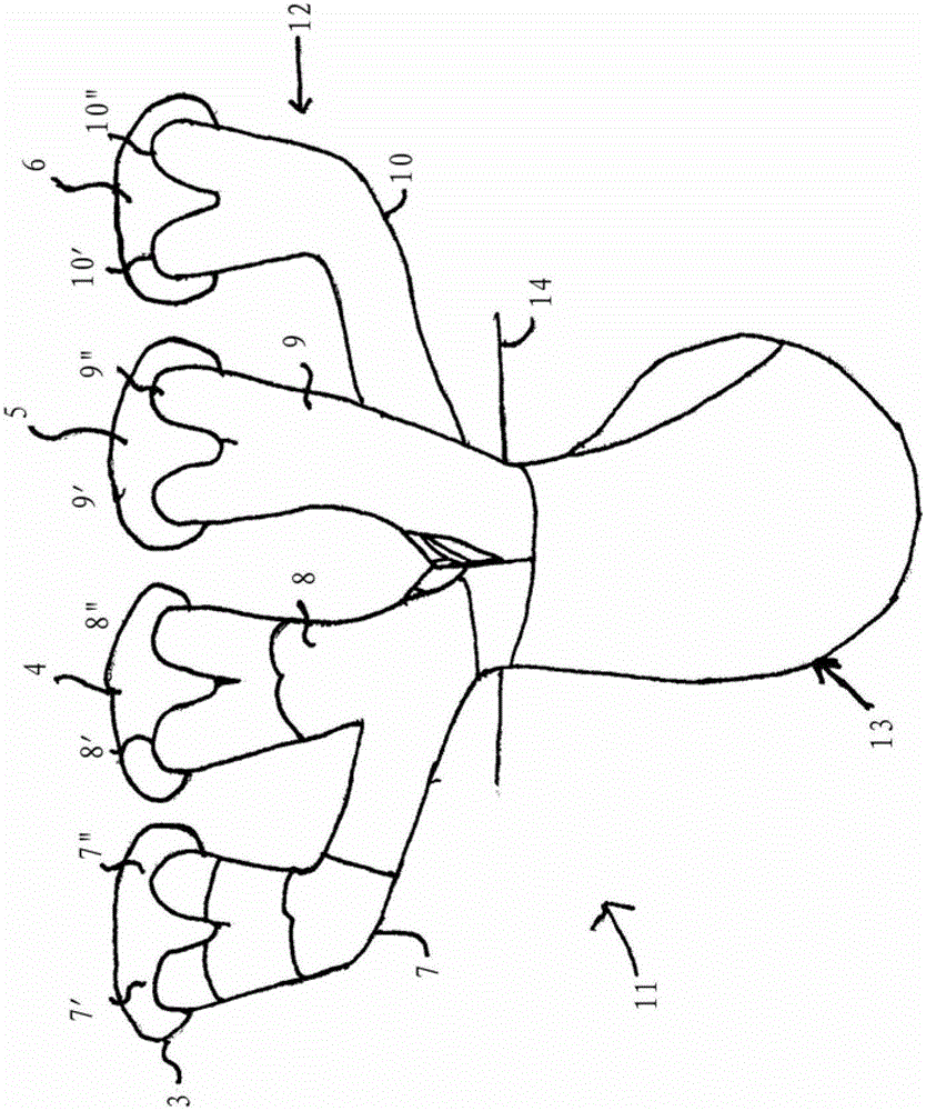
[0038] The four cylinders 3, 4, 5, 6 are respectively connected to the flow passages 7, 8, 9, 10 of the exhaust system 11 of the internal combustion engine 1, through which the exhaust gas produced by the combustion reaction in the cylinders passes. leads to figure 1 Catalyst not shown. The flow channels 7 , 8 , 9 , 10 are integrated in the cylinder head 2 and form part of an exhaust manifold 12 integrated in the cylinder head 2 . However, the exhaust system according to the invention is not restricted to internal combustion engines with 4 cylinders, but can also be used in internal combustion engines with fewer or more than 4 cylinders.

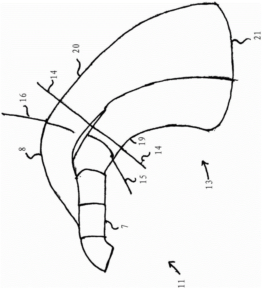
[0039] The exhaust system 11 has, in addit...


PUM


Abstract

An exhaust system for a combustion engine (1) having a plurality of cylinders (3,4,5,6), a cylinder head (2) and an engine block is provided. The exhaust system comprises an exhaust manifold, which is integrated in the cylinder head (2), flow channels (7,8,9,10), and an exhaust pipe (12), which is connected to a head flange (14) of the cylinder head (2). The flow channels (7,8,9,10) each extend from one of the cylinders (3,4,5,6) to a head flange (14). At least two of the flow channels (7,8,9,10), which are connected to cylinders (7,8,9,10) that are not ignited in succession, are united within the cylinder head (2) and form a common flow channel (15). At least one further flow channel (16), which is connected with a cylinder (4) ignited in succession, is routed separately as far as to the head flange. The common flow channel (15) is united with the further flow channel (16) only in the exhaust pipe (13,13').

Description

technical field [0001] The invention relates to an exhaust system for an internal combustion engine, an internal combustion engine with the exhaust system and a vehicle with the internal combustion engine. Background technique [0002] Internal combustion engines are usually equipped with an exhaust system by means of which the exhaust gases generated in the internal combustion engine or in the cylinders of the internal combustion engine are discharged. The exhaust gas flows from the respective cylinders via an exhaust manifold to a joint outlet and is then directed to a catalytic converter, where unnecessary parts of the exhaust gas are removed or converted into non-toxic substances. [0003] The waste gas trap can be produced as a separate part which is mounted on the cylinder of the internal combustion engine by means of screws or the like. The waste gas trap is arranged free-standing towards the outside air and is designed as a component independent of the cylinder head...

Claims


Application Information

Patent Timeline
Patent Type & Authority Applications(China)
IPC IPC(8): F02F1/42F01N13/10
CPCF01N13/10F01N2470/30
Inventor P.西格M.简克M.克莱因
Owner GM GLOBAL TECH OPERATIONS LLC
Why Eureka
Try Eureka