
Laser-induced fluorescence combustion field parameter measuring device

A laser-induced fluorescence and parameter measurement technology, applied in the field of optical measurement, can solve the problems of uneven light intensity distribution and low measurement accuracy of two-dimensional parameters of the combustion field, meet the requirements of light intensity uniformity, improve environmental adaptability, and is convenient The effect of reasonable layout

Inactive Publication Date: 2013-04-24
NORTHWEST INST OF NUCLEAR TECH
View PDF11 Cites 17 Cited by
  • Summary
  • Abstract
  • Description
  • Claims
  • Application Information

AI Technical Summary

Problems solved by technology

[0010] The purpose of the present invention is to provide a laser-induced fluorescence combustion field parameter measurement device, which overcomes the problem of low measurement accuracy of the two-dimensional parameters of the combustion field caused by the uneven distribution of the two-dimensional light intensity of the excitation laser in the existing measurement device, and satisfies strong vibration , The demand for two-dimensional parameter measurement of the combustion field under the impact of strong noise

Method used


Image

  • Laser-induced fluorescence combustion field parameter measuring device
  • Laser-induced fluorescence combustion field parameter measuring device
  • Laser-induced fluorescence combustion field parameter measuring device

Examples


Embodiment Construction

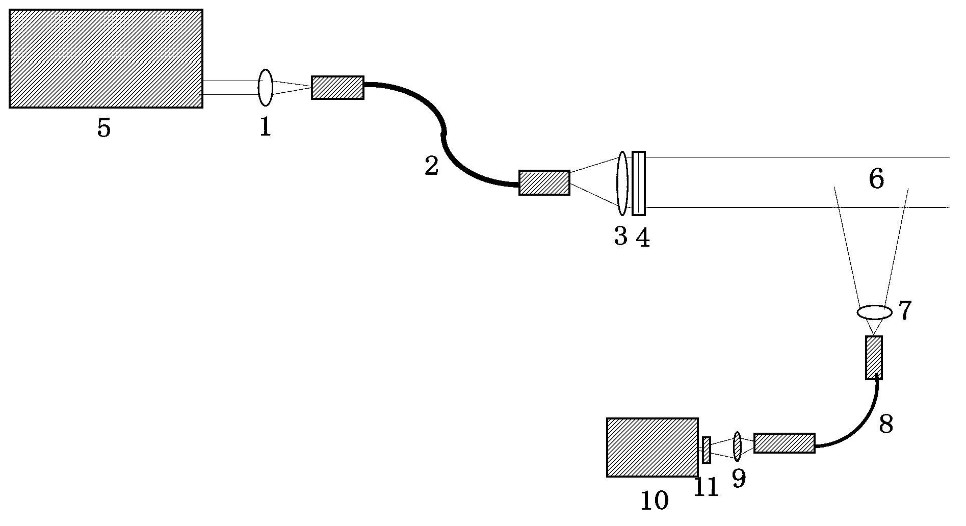
[0035] like figure 1 As shown, the laser-induced fluorescence combustion field parameter measurement device of the present invention includes a light source system and a detection system. The light source system includes a laser 5 and a fiber coupling lens 1, a shaped fiber bundle 2, a spherical lens 3 and a cylindrical lens 4 arranged in sequence along the laser transmission direction, wherein the shaped fiber bundle 2, spherical lens 3 and cylindrical lens 4 are mainly used to combine The surface spot of the laser output is shaped into a uniform surface beam 6 for the measurement of the two-dimensional parameters of the laser-induced fluorescence combustion field, so as to meet the requirements for the measurement of the two-dimensional parameters of the combustion field. The detection system includes a signal collection lens 7 , a detection fiber bundle 8 , a coupling lens 9 and an imaging device 10 sequentially arranged along the detection optical path.

[0036] The excit...


PUM

PropertyMeasurementUnit
diameteraaaaaaaaaa
lengthaaaaaaaaaa

Abstract

The invention discloses a laser-induced fluorescence combustion field parameter measuring device which comprises a light source system and a detection system, wherein the light source system comprises a laser (5), an optical fiber coupling lens (1), a plastic optical fiber bundle (2), a spherical lens (3) and a cylindrical lens (4), wherein the optical fiber coupling lens (1), the plastic optical fiber bundle (2), the spherical lens (3) and the cylindrical lens (4) are arranged in the laser transmission direction in sequence; an optical fiber configuration section on the incident end surface of the plastic optical fiber bundle (2) is matched with a light beam section of the laser (5), and the emergent end surface of the plastic optical fiber bundle (2) is configured into a linear shape; and a cylindrical center line of the cylindrical lens (4) is parallel to an optical fiber configuration line on the emergent end surface of the plastic optical fiber bundle (2). The laser-induced fluorescence combustion field parameter measuring device has the benefits that a lamellar light beam with uniform light intensity in an area on the light beam transmission direction is realized, the demands that the combustion flow field two-dimensional parameter measurement is realized by adopting a planar laser-induced technology are satisfied, the combustion flow field parameter measurement under the strong-vibration and strong-noise impact environment are simultaneously satisfied, and the environmental adaptability of the system is improved.

Description

technical field [0001] The invention belongs to the field of optical measurement, in particular to a laser diagnosis device for measuring combustion flow field parameters. Background technique [0002] Laser-induced fluorescence technology is a relatively advanced measurement technology in flow field diagnosis. Its basic principle is that molecules in the ground state transition to the excited state after resonantly absorbing photons of corresponding energy, and then radiate fluorescence while transitioning downward. [0003] The intensity of the fluorescent signal can be expressed by formula (1): [0004] I LIF =cnI L Φ (1) [0005] Among them, c represents the proportionality coefficient, n is the particle number of the detected particle at the specific energy level of the ground state, and I L represents the intensity of the excitation laser, and φ represents the quantum efficiency of the fluorescence. [0006] It can be seen from the above formula that the fluoresce...

Claims


Application Information

Patent Timeline
Patent Type & Authority Applications(China)
IPC IPC(8): G01N21/64
Inventor 张振荣王晟李国华邵珺张立荣叶锡生
Owner NORTHWEST INST OF NUCLEAR TECH
Learn More