A Ratio Method for Correcting Terrain Influence in Electromagnetic Exploration
A terrain and ratio technology, applied in the field of electrical and electromagnetic prospecting, can solve the problems of poor correction effect, cumbersome implementation, and large amount of calculation, and achieve the effects of avoiding the introduction of errors, improving the correction effect, and saving the model building process
- Summary
- Abstract
- Description
- Claims
- Application Information
AI Technical Summary
Problems solved by technology
Method used
Image
Examples
Embodiment 1
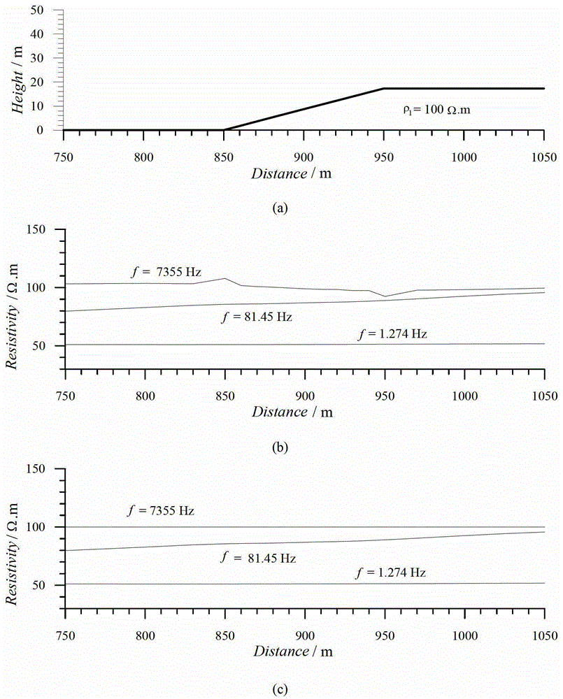
[0038] Simulation of pure terrain effect correction for CSAMT uniform earth, uniform earth resistivity ρ 1 =100Ω·m, using electric dipole source and boundary element numerical simulation electric field E x Component, the far field apparent resistivity definition.
[0039] Step 1. Since this example is a pure terrain response simulation of a uniform earth, the surface resistivity is the same as the uniform earth resistivity, so the uniform earth resistivity ρ 1 =100Ω·m as the standard resistivity ρ for terrain correction standard (i);
[0040] Step 2, draw topographic profile 1(a) and apparent resistivity profile figure 1 (b) for comparison. The basic law of the influence of topography on CSAMT is: the apparent resistivity profile curve is opposite to the change of topographic relief, that is, the apparent resistivity rises when the topography descends, decreases when the topography rises, and the apparent resistivity changes sharply when the topography changes sharply.
...
Embodiment 2
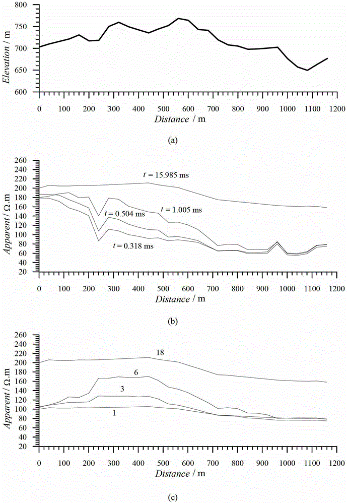
[0046] Example 2. Topographic correction of measured TEM mountain exploration data, center loop device: transmitting wire frame 600m×600m, receiving coil equivalent area 100m 2 , observation time 30ms, 20 channels.
[0047] Step 1: Obtain the surface resistivity value of each measuring point without terrain influence by applying the small pole moment DC resistivity method, as shown in Table 2.
[0048] Table 2 The surface resistivity values of each measuring point obtained by the small pole moment DC resistivity method
[0049] Measuring point / m
Resistivity / Ω.m
Measuring point / m
Resistivity / Ω.m
Measuring point / m
Resistivity / Ω.m
Measuring point / m
Resistivity / Ω.m
0
100.00
320
104.00
640
94.000
960
81.242
40
103.10
360
104.50
680
90.750
1000
80.700
80
102.26
400
105.00
720
87.500
1040
80.250
120
102.25
440
105.62
7...
PUM
 Abstract
Description
Claims
Application Information
 - R&D
- Intellectual Property
- Life Sciences
- Materials
- Tech Scout
- Unparalleled Data Quality
- Higher Quality Content
- 60% Fewer Hallucinations
Browse by: Latest US Patents, China's latest patents, Technical Efficacy Thesaurus, Application Domain, Technology Topic, Popular Technical Reports.
© 2025 PatSnap. All rights reserved.Legal|Privacy policy|Modern Slavery Act Transparency Statement|Sitemap|About US| Contact US: help@patsnap.com


