
Subsection space aligning method based on homography transformational matrix

A homography transformation and spatial alignment technology, applied in image analysis, image data processing, instruments, etc., can solve problems such as cumbersome calculation process, large range, and easy introduction of errors

Active Publication Date: 2013-04-24
BEIJING INSTITUTE OF TECHNOLOGYGY
View PDF4 Cites 34 Cited by
  • Summary
  • Abstract
  • Description
  • Claims
  • Application Information

AI Technical Summary

Problems solved by technology

At present, in the traditional space alignment method, within the calibrated distance range of 20 meters, at different distance points, the points on the target are randomly detected, and the coordinate system expression of the target in the camera and the coordinate system in the radar coordinate system are respectively obtained. Expression, according to the data acquired by the two sensors, the camera internal parameter matrix composed of scaling factor, focal length, etc., and the camera external parameter matrix composed of rotation matrix and translation vector are estimated. The calculation process is cumbersome and easy to introduce errors; in addition, When solving the transformation matrix for a target with a calibration distance of more than 20 meters according to the above algorithm, due to the large range, there is a huge error, which leads to the failure of spatial alignment

Method used


Image

  • Subsection space aligning method based on homography transformational matrix
  • Subsection space aligning method based on homography transformational matrix
  • Subsection space aligning method based on homography transformational matrix

Examples


Embodiment Construction

[0040] The present invention will be described in detail below with reference to the accompanying drawings and examples.

[0041] The present invention provides a method for segmented spatial alignment based on a homography transformation matrix, comprising the following steps:

[0042] Step 1: Establish the relationship between the camera coordinate system and the millimeter-wave radar coordinate system based on the homography transformation matrix:

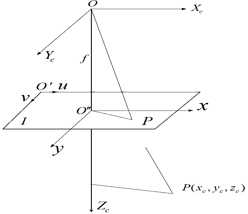
[0043] like figure 1 Shown, OX c Y c Z c Represents the camera coordinate system, the origin O is located at the optical center of the camera; X c The axis is parallel to the scanning line direction of the camera, pointing to the direction in which the scanning pixels increase; Y c The axis is perpendicular to the scanning line direction of the camera and points to the direction in which the scanning line increases; Z c The axis is perpendicular to the imaging plane and points in the direction of the camera line of sight. ...


PUM


Abstract

The invention discloses a subsection space aligning method based on a homography transformational matrix. According to the subsection space aligning method based on the homography transformational matrix, large marked distance is sectioned, the homography transformational matrix between a camera coordinate system and a millimeter-wave radar coordinate system of each subsection is acquired, errors caused by using a same homography transformational matrix to represent coordinate relations of two sensors in the prior art are avoided, and space aligning of target detection of the large marked distance can be achieved. Relations of different coordinate systems between the camera and the millimeter-wave radar are deduced and represented, and finally the relations of the coordinate systems between the camera and the millimeter-wave radar are represented by the homography transformational matrix N. The two sensors are used for obtaining target data and solving the homography transformational matrix N, and a camera internal parameter matrix and a rotation matrix which are composed of solving scaling factors, focal distance and the like are avoided and a camera external parameter matrix composed of translation vectors is avoided. Therefore, operation process is greatly simplified and operation time is saved.

Description

technical field [0001] The invention relates to the technical field of multi-sensor information fusion of unmanned vehicles, in particular to a segmented space alignment method based on a homography transformation matrix. Background technique [0002] Unmanned vehicles, also known as outdoor intelligent mobile robots, are highly intelligent devices that integrate environmental perception, dynamic decision-making and planning, behavior control and execution. It is inseparable from multi-sensor information fusion technology. Multi-sensor information fusion technology is that the computer makes full use of the resources of each sensor, through the reasonable control and use of various measurement information, and combines complementary and redundant information in space and time according to a certain optimization criterion, resulting in an accurate observation of the observation environment. Consistent explanations or descriptions, while generating new fusion results. In the...

Claims


Application Information

Patent Timeline
IPC IPC(8): G06T7/00
Inventor 付梦印靳璐杨毅宗民
Owner BEIJING INSTITUTE OF TECHNOLOGYGY
Learn More